We don’t normally embrace the supernatural here at Hackaday, but when the topic turns to the radio frequency world, Arthur C. Clarke’s maxim about sufficiently advanced technology being akin to magic pretty much works for us. In the RF realm, the rules of electricity, at least the basic ones, don’t seem to apply, or if they do apply, it’s often with a, “Yeah, but…” caveat that’s sometimes hard to get one’s head around.
Perhaps nowhere does the RF world seem more magical than in antenna design. Sure, an antenna can be as simple as a straight piece or two of wire, but even in their simplest embodiments, antennas belie a complexity that can really be daunting to newbie and vet alike. That’s why we were happy to recently host Karen Rucker’s Introduction to Antenna Basics course as part of Hackaday U.
The class was held over a five-week period starting back in May, and we’ve just posted the edited videos for everyone to enjoy. The class is lead by Karen Rucker, an RF engineer specializing in antenna designs for spacecraft who clearly knows her business. I’ve watched the first video of the series and so far and really enjoy Karen’s style and the material she has chosen to highlight; just the bit about antenna polarization and why circular polarization makes sense for space communications was really useful. I’m keen to dig into the rest of the series playlist soon.
The 2021 session of Hackaday U may be wrapped up now, but fear not — there’s plenty of material available to look over and learn from. Head over to the course list on Hackaday.io, pick something that strikes your fancy, and let the learning begin!


Look like a good watch.
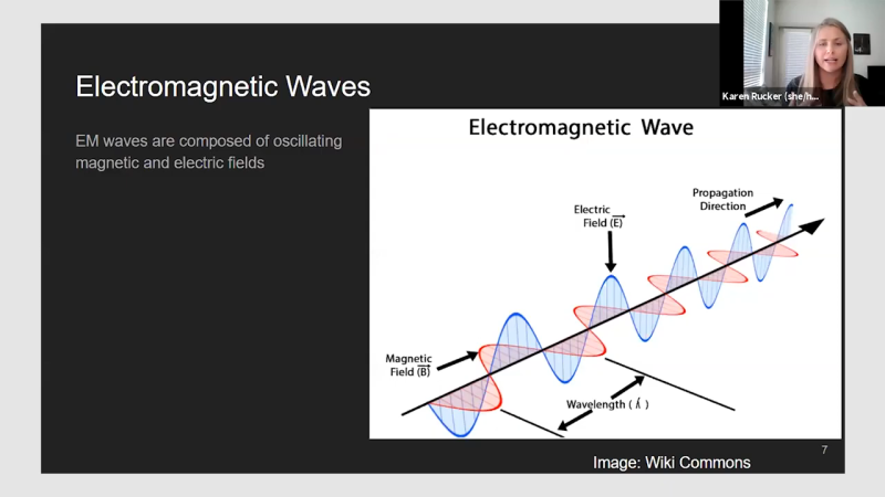
What surprises me in the electromagnetic wave diagrams is that the E and B fields seem to be “in phase”.
Intuitively it would be the rate of change of E that produces B (so a peak of B would line up with a zero-crossing of E) and vice versa, when B is changing most rapidly (zero crossing) I might expect the E to peak.
All diagrams I just googled seem aligned likewise, so it seems a common consensus. I suppose I’ll have to do this the hard way and solve Maxwell’s equations to get to the bottom of this – unless there’s a cheat’s explanation?
Electromagnets
I, too, have wondered about this (for 50 years…) , and I agree with abjq – I don’t understand why the two fields aren’t 90 deg out of phase. If they were, then the energy flow wound be continuous, only changing form from magnetic to electric, in a rotational form – sort of energy spiraling through space. I would love if someone could explain this.
I found this 9 page paper, https://arxiv.org/pdf/2003.06510.pdf “Plane-wave solutions of Maxwell’s equations:
An educational note”. It argues that the standard method of teaching EM using monochromatic plane-wave can, and should be generalized to general plane waves, not just monochromatic ones.
Using monochromatic plane waves, it derives that the E and B are proportional to each other in about a page. The basic idea is that if you take the equations for monochromatic plane waves and then plug them into Maxwell’s Equations, the 4 equations simplify to say that E and B are both perpendicular to the direction of propagation, and perpendicular and proportional to each other.
The generalized version takes 3 pages, and follows the same idea. The last 3 pages do it again with a conducting medium.
Thanks for the reference. Will study and report back.
That is what happens in circular polarization.
Intuition is easily confused because usually we see electric and magnetic fields as a loop, and according to Faraday’s law of induction, the derivative of magnetic field is in relation to curl of the electric field. But for a wave propagating in free space, the curl of the electric field is not easy to imagine.
@Telford Dorr said: “I, too, have wondered about this (for 50 years…) , and I agree with abjq – I don’t understand why the two fields aren’t 90 deg out of phase. If they were, then the energy flow wound be continuous, only changing form from magnetic to electric, in a rotational form – sort of energy spiraling through space. I would love if someone could explain this.”
Without some form of charge storage present (e.g. capacitive and/or inductive), the B (magnetic) and E (electrical) fields should be physically orthoginal and in-phase time-wise. In Newtonian physics I think the gem of a paper cited earlier by “Buddha Buck” proves this nicely.
Neither field generates the other:
https://physics.stackexchange.com/questions/181277/do-the-electric-and-magnetic-components-of-an-electromagnetic-wave-really-genera
https://physics.stackexchange.com/questions/228796/how-can-one-meaningfully-say-that-one-field-generates-the-other-in-an-em-wave
Maxwell’s equations say that the curl (or closed line integral in macroscopic form) of the electric field is proportional to the time derivative of the magnetic field; same for the curl of the magnetic field.
∇×E = -∂B/∂t
∇×H = J + ∂D/∂t
The curl of the field isn’t the field.
Imagine looking at a clock. If one hand representing the E field points to 12 o’clock and the other representing the B field points to 9 o’clock the wave will be traveling away from you.
If the B field is pointing to 3o’clock the wave will be traveling towards you.
This orthogonality is what gives the wave velocity.
Right-Hand Rule[1]
1. https://en.wikipedia.org/wiki/Right-hand_rule
HackadayU as an organized, cohesive thing has somehow, up to this point, escaped my notice.
https://hackaday.io/u/
https://calendar.google.com/calendar/u/0/embed?src=superconference@hackaday.io&pli=1
Magical is a fitting description, it isn’t just related to antennas, but it starts in the lowest power levels where signals are generated. In the past with open frame circuitry using vacuum tubes as it was before solid state components and printed circuit boards, RF propagation has required advancements in designs as simple as where to route conductor traces to eliminate efficiency loses due to unintended capacitance and impedance, multi layer PC boards implementing ground planes, shielding of conductors and components, SMD components to also reduce or eliminate RF loses encountered with through hole type components. I remember my first encounters with high power RF stuff when I saw my first RF wave guides. I was fascinated with how they looked and worked. I used to look at RF circuits assembled as DEAD BUG and UGLY BUG when I was much younger and simply wonder how and why, did they work. It was all magical. The things we know are around us but cannot see ! And then there are those things we can see with the right equipment.
This might be of interest: https://en.wikipedia.org/wiki/Evolved_antenna
i still don’t understand any of it really but i decided to learn about antennas from a more theoretical level (i didn’t make it very far). but the one thing i found is this formula that gives the resistance as a function of the wavelength and the length of wire. i played with it a little bit and became convinced it really says that at even multiples of the wavelength (or half wavelength?) the resistance is 0 and at odd multiples it’s infinite. in a boring wire, no components (i think one end driven and one end grounded?).
i’m convinced that insight was true and if you think about it i think it’s possible to make some sense out of it. but it’s still pretty crazy. eye-opening, i guess.
keep in mind, a 60hz signal has a wavelength of 5000km! i think this showed up in one of the articles here about transmission grids…
Wow!
This is a must watch for me! Looking forward to watch it when the time comes.
Isotropic antenna has a gain of 1, or 0dBi in decibels, but not “1dB”.
A gain of 1 is 0dB (no ‘i’). The ‘i’ in 0dBi means the gain is 1 relative to an isotropic antenna *by definition*. A subtle but important distinction in the notation.
To say an isotropic antenna has a gain of 0dBi is technically but tautologically correct.
I agree, it is a tautology, but nevertheless it is unhelpful (and possibly incorrect*?) to specify antenna gains in “dB” alone – there should always be some implied reference radiator, e.g. dBi, dBd, dBic, etc. And in any case it’s not _1_dB – which was the point I was trying to make. :)
*although the IEEE definition seems to imply that gain always means w.r.t. isotropic, so presumably decibel gain ‘dB’ should be assumed to mean dBi (or dBic).
Here is my 2 cents on the topic… not a rigorous explanation but it should take a lot of the magic and mystery out of the math explanations :
http//www.silcom.com/~pelican2/WAVEZ.doc
( this is a MsWord document… this is an article I wrote some years ago )
The electric and magnetic fields are not 90 degrees out of phase because the energy is traveling at the speed of light… it is not “stationary” as it would be in an ordinary inductor or capacitor.
I won;t try to explain more about this here… I don’t completely understand it either, but I can see that explaining this stuff entirely only using advanced calculus is probably a mistake… specific examples can be explained with methods that are a lot simpler and more intuitive… like the one I offer in my paper.
Signing up to get replies for my blog post seems to be a real pain… I give up… Send e-mails directly to me :
pelican2@silcom.com
Thanks
For Linux users, xnec2c is a useful and free antenna design program. Expect to spend about a day learning to use it. Complex designs can take a while to run, so a modern high performance CPU is a good idea.