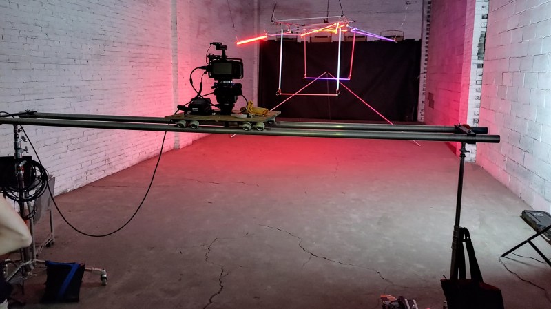
A camera dolly can be fantastic filmmaking tool, and [Cornelius] was determined to create his own version: the “Dope” DIY Dolly. The result not only upped his production quality, but was also entirely in line with his DIY approach to filmmaking in general.
 A basic dolly design is straightforward enough: a flat platform with wheels, and some aluminum tubing upon which to roll. But while dolly assemblies are easy to purchase or rent, [Cornelius] found that his DIY version — which used easily sourced parts and about 80 hours worth of 3D printing — provided perfectly acceptable results, while opening the door to remixing and sharing with like-minded filmmakers.
Interested? Download the STL files to get started on your own version. As for the track, smooth metal pipe is best, but sometimes track made from PVC can do the job. [Cornelius] has a few additional STL files for those planning to make a base from 1″ PVC pipe, and those are on a separate download link near the bottom of the project page (here’s that link again.) Watch the Dope Dolly in action in the brief video embedded below.
On the other hand, if you prefer your DIY camera equipment to be on the smaller and more complicated end of the spectrum, be sure to check out this multi-axis camera slider.


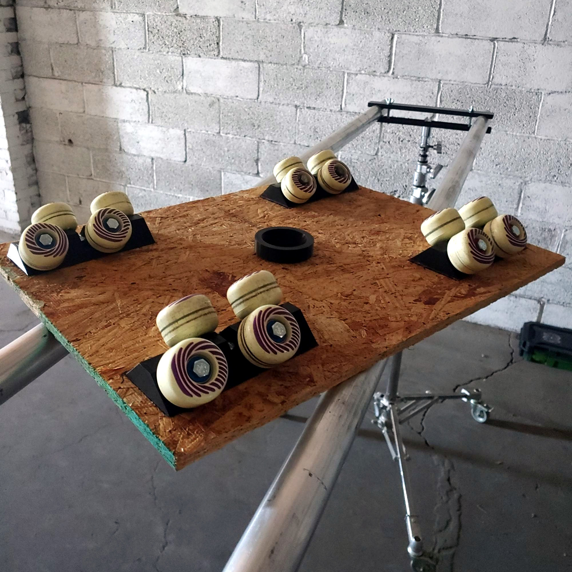
Interesting. Seriously overconstrained. I wonder how much smoother it would be with eleven fewer wheels.
Compliance is a thing.
If the wheels were granite, i’d worry about overconstraint. If the deck were A surface plate, I’d worry.
EVERY part of this is compliant. It is likely much smoother than if the 11 wheels were removed
All the wheel-rail contacts are only semi-constrained, with gravity pulling it down. If any of the wheels is out of alignment, it will just not contact the rail and will not affect the motion.
You think this should have 5 wheels?
I would say it was a typo but you spelled out ‘eleven’ so I am unsure where the 5th wheel should go after the first 4 contact the rails.
Since you’re concerned about over constrainment, I guess it should just be able to rotate freely somewhere out of the way so that there’s no possibility of it adding any sort of constraint to the assembly. Maybe upside down on the top?
/s
Formally, this is a rigid body with a single degree of freedom for motion (one linear) of the six available: three linear, three rotational (x, y, z, pitch, roll, yaw)
Each roller provides a single constraint normal to the line from the axis of the wheel, through the point of contact, through the axis of the rod, so sixteen wheels provides sixteen constraints.
Make sense?
Only this is not a rigid body. It is a compliant body (the wheels are compliant, the board is compliant, and so on), equivalent to sprung wheels or an equalizing suspension (or whiffletree) such as used on many crawler tractors or a military tank.
So, the original point, though correct in the sense of statics-101, doesn’t really apply here. As mentioned in a number of comments, this allows for a certain averaging of any imperfection in the rails, again, like the suspension for a crawler.
If you want to know a minimal constraint solution, there are many. A simple one is four wheels on one rail (providing z and y linear constraint, as well as stopping pitch and yaw), two at each angle, and a single wheel on the other rail (either angle, or straight up, to prevent roll), leaving x free for motion. This would be a rough ride, though.
I understand that. I was poking fun at the statement that there should be 11 fewer wheels.
There are 16 wheels riding on the two rails, 4 at each corner. If they want 11 fewer wheels that means that one corner gets an additional wheel. Except that they explicitly mentioned over constrainment because of there being too many wheels. I jokingly took that to mean that there should only be one wheel in contact with the rails at each corner and that a 5th wheel was hanging out somewhere that it could not possibly contribute to any constraints.
Also, I used /s at the bottom, which is used to explain sarcasm since it is hard to tell over text alone.
Looks really nice. Too fancy for my camera needs, so take it with a grain of salt when I say the 80hrs of 3d printing seems nuts. Assuming you get it right on the very first print [and assuming three more times depending on your bed size] and can accurately align all four, it struck me how much quicker and possibly cheaper it might be to cut some wood or even use some predrilled angle iron; both of which would reduce alignment issues and increase both rigidity and weight for vibration dampening…but that is a mostly uninformed suggestion. The project is super cool. Just wish I had a need for one.
yeah that was just what i was thinking. on a project like this i’d 3d print corner brackets or alignment shims, i certainly would not print the bulk material like they did here. but it apparently takes all kinds!
You probably don’t want it any more rigid than this, as the whole thing needs some compliance to even out the imperfections… Certainly with the right tools could be made precisely enough to run well and much quicker than 3d printing – but as the saying goes if all you have is a hammer everything looks like a nail. The 3d print is convient if you have one – a good printer even more so as check the first layer has stuck properly and come back when its done then., and if you lack the mitre/table saw that would help hugely in creating repeatable angle cuts, or any of the other tools that more serious woodworkers would have to make every part matching afterwards – like massive clamps and a good plane…
The weight might be a good thing – but there comes a point when its inertia makes it hard to use, and its weight will bend the rails to a noticeable degree – its not a certain win.
Very few people need any of the photography equipment they collect – you do it because you enjoy it, so don’t let that put you off projects like this. Though might I suggest smaller can work well – heck even build it in something like Lego so you can tweak it to fit your needs – assuming you are building one to a scale that any construction toy is capable of.
We made one of these when I was studying film production, except we called it a “pipe dolly”, and it worked fine with PVC pipe.
One of the reasons for the rails or pipe, and so many wheels, is smoothness of travel. Every little bump, every imperfection would be transmitted to the camera. Each glued seam in the pipe needed sanding until smooth, ditto the skate wheels. Spreading out the load, i.e. less load on each axle, reduced the effect of imperfections. Same reason for the offset pairs. If you left a slight imperfectin in a seam, there’d be 2 small bumps, instead of one big one. That’s also why train track joins are offset.
Of course now, with in-camera stabilisation, some of those considerations are less important.
Anything that “revealed” the camera, such as bumpy or jerky travel, is considered to be breaking the fourth wall. You don’t want the audience to be able to perceive the camera. The goal is make it seem like we’re watching with our own eyes, not through the viewfinder.
Instead of 80hrs of printing, would the use of cut wooden beams or pre-drilled angle iron simplify wheel alignment and assembly, be faster to make, improve rigidity and increase load bearing of the deck while adding weight that dampens bounces due to rail/wheel imperfections?
I’ve built something similar – metal broom handles provided suitable rigidity very cheaply, and a slider padded with felt furniture pads provided a suitably constrained solution.
I then added a stepper and toothed belt for automated control.