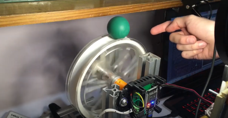
If you march sufficiently deep into the wilderness of control theory, you’ll no doubt encounter the inverted pendulum problem. These balancing acts have emerged with a number of variants over the years, but just because it’s been done before doesn’t mean there’s no space for something new. Here, [David Gonzalez], has taken this classic problem and given it an original own spin–literally–where the balancing act is now a ball balanced precariously upon a spinning wheel. (Video, embedded below.) Mix in a little computer vision for sensing, a dash of brushless motor control, a bit of math, and you have yourself a closed-loop system that’s bound to turn a few heads.
[David’s] implementation is a healthy mix of classic control theory with some modern electronics. From the theory bucket, there’s a state-space controller to drive both the angle and angular velocity of the ball to zero. The “state” is a combination of four terms: the ball angle, the ball’s angular velocity, the wheel angle, and the wheel’s angular velocity. [David] weights each of these terms and sums them together to create an input value to adjust the motor velocity driving the wheel and balance the ball.
From the electronics bin, [David] opted for an ESP32 running Arduino, the custom Janus Brushless Motor Controller running SimpleFOC, and a Maix Bit Microcontroller with an added camera running MicroPython to compute the ball angle. Finally, if you’re curious to dig into the source code, [David] has kindly posted the firmware on Github.
We love seeing folks mix a bit of control theory into an amalgamation of familiar electronics. And as both precision sensors and motor controllers continue to improve, we’re excited to see how the landscape of projects changes yet again. Hungry for more folks closing the loop on unstable systems? Look no further than [UFactory’s] ball balancing robot and [Gear Down for What’s] two wheeled speedster.


Oooh. Engineering Pr0n!
It was not obvious to me at first but a difference from a regular inverted pendulum is the rotational momentum of the ball. You can see this in the demos toward the end of the video. After spinning the system up to get the ball back on top, it wants to “roll over” the top to the other side on its own.
Isn’t this another implementation of PID?
You do not want integral term in this particular case. PD² should work as far as I remember.
Ooh; this is a great question, and one I’ve had myself before! The short answer is no, but in this problem the control law looks very similar to a PID controller.
PID works great for setups that have a single input and single output (SISO), but it breaks down when you have any flavor of Multiple Inputs and/or Multiple Outputs (MIMO). Controllers based on State Space Representations really shine in that second category. State space representations use a model of the system and a collection of internal variables called “the state” that get updated together to produce an output.
But, depending on representations, esp for simple systems, both PID controllers and state space controllers can actually produce a control law (the “u = sum of weighted terms” stuff) that either look very similar or are completely identical. In this example, the output looks eerily similar to a PD controller where the error is proproportional to the error in ball angle and ball angular rate when the setpoint is set to zero. But there’s an extra two terms that are being added, which are proportional to wheel angle and wheel velocty when their setpoint is set to zero. This comes from the state space representation where there are multiple (4) outputs: ball angle, ball angular velocity, wheel angle, and wheel angular velocity. (Side note: the wheel angle term is set to zero in the code, which is why the video just shows three terms.) The result is that our control law isnt just trying to drive the ball angle to zero, it’s trying to *also* drive the ball velocity and wheel angular velocity to zero simultaneously with a single input. That’s our “single-input, multiple-output” system that requires a state space representation. (Side note: the technique in this problem is called “Full State Feedback,” because all terms from the state are being incorporated to use produce a control input to stabilize the system.)
You might think: hey, can’t I just stare at the problem and hack together a weighted sum of PID terms from different systems that does the same thing? And hey, sure, why not? But the beauty of state space representations is that there’s a cookbook way to do that for systems that get *super* complicated in ways that aren’t intuitive–and better–using that representation also lets you make guarantees about the stability of that system across a range of inputs.
I hope this helps! And someone who’s wayy more seasoned in control theory should certainly chime in.
Aside: I’d love to write about this stuff in some original posts, but I’m struggling trying to find ways to introduce it in a way that’s friendly. But I haven’t given up on that dream just yet. This stuff really is magic!
I’d read the hell out of those posts.
Me too
Wow! What a great answer. Thanks for taking the time to write such an excellent explanation.
Me three. I’m wondering how cnc machines coordinate 2 or 3 axis while using PID instead of step/dir & stepper motors.
My theory is that they are so geared down that a PID can actually have a little error (which pids normally have) yet the output can still be within .05mm etc.
Any ideas?
I think it’s more that each axis is orthogonal, so almost no energy/momentum is transferred between them, and they are independent. At that point the SISO theory is sufficient.
With a integral term (the I term in PID) the error should go to zero. But it depends also on your feedback (encoder or position measurement). Your gear train will have some play so then you really have to control on the output or use a compensation.
Thanks that’s a really good explanation especially to someone who has no experience with PID controllers.
I second the greatness of the answer ++
Worked briefly at a startup where the founder belived AI was the asnwer to everything. Somehow he convinced investors that conventional control systems were almost impossible to tune (having built lots and not being an AI guy, somewhat disagreed). So he got me to built an inverted pendulum bot (rather than use the one I purchased for my daughter which used almost all the same kit but didn’t have a built in raspberry pi – local compute was desired).
After lots of training in a virtual environment, it was moved over to the bot to prove the system could cross the reality gap. My goodness did it wobble in a most unstable way and need a big weight mounted to the top to dampen things a bit. Rather showing at least to me that a conventional control system would have worked nicely. For a mental image of it – one outsider of the company termed it “parkinsons bot” (and I can mention that as I shake some of the time).
Somehow it filled the founder with self belief and the next step appears to be walking robots. Needless to say I do something else now.
Long live conventioanl control systems, people implimenting them and useful solutions to actual problems!
I do wish the company well. But would rather spend my single life working on stuff I can get behind.
Control systems like these, when explained well and implimented correctly are excellent solutions. They’re not little black boxes. By doing and implimenting projects like this, people learn very useful things.
Next up – controlling it in 2 axis! I’m picturing a “snow man” type setup, with a large sphere at the bottom spun in 2 axis via friction wheels below it. Small green ball is balanced on top of the large sphere, and the camera could be moved overhead looking down to track the X & Y of the green ball.
I had the opportunity a few (err… 10) years ago to wisit the structural lab at Columbia. They have a shaking table there on which they realized a 3-ball snowman setup. Just giving ideas for the case you are done with the 2-ball setup ;-)
Look how the Butterfly Robot works when a ball rolls over a curved shape https://youtu.be/kyvW5sOcZHU
Love to see it balance on a sphere
I wondered why the sudden traffic in this video. Thank you, this is awesome ;)