Need a steel beam? You can 3D print PLA beams that are as strong as a steel beam of equivalent weight according to [RepRap]. The Python code for FreeCAD generates a repeating structure especially well suited for belt printers that can print a beam of any length. Keep in mind, of course, given two things that weigh the same, if one is made of steel and the other PLA, the steel one will be physically smaller.
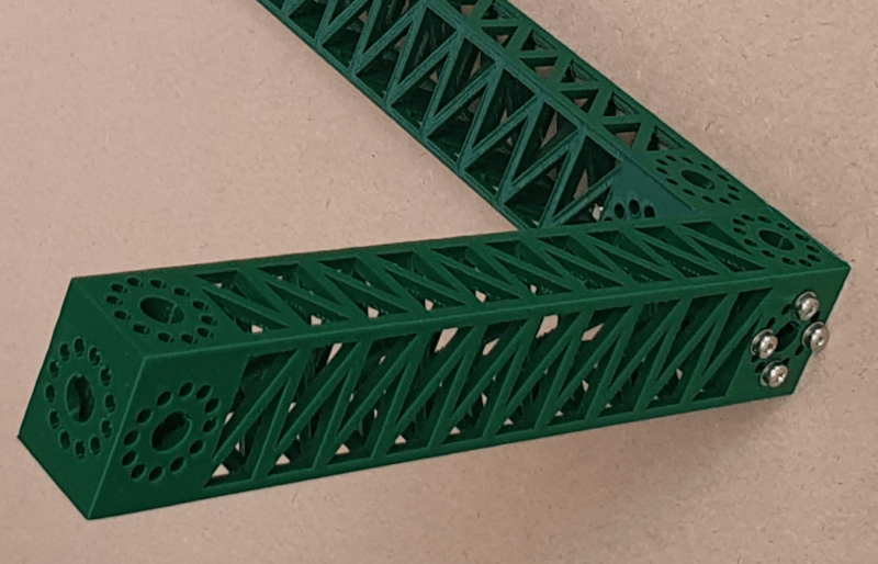
The beams are repeating tetrahedrons which are quite strong with a lot of material on the outer faces to resist bending. Each beam end has a neat block with a wiring hole and a ring of small holes that allow you to mount the beams to things or each other with 30 degree increments of rotation.
Turns out, these holes are a mess for the FreeCAD geometry engine to deal with, so the script actually does what we can only call a hack. It randomly changes the size of the cut cylinders. The change is too small to be noticeable on the final print, but large enough to break the uniformity that upsets the software.
You don’t have to have a belt printer to make these beams, but if you don’t, you can only print one as long as your print bed. We wonder if we’ll start seeing 3D printers built using these beams as frame elements? It would seem to make sense.
If this gives you the urge to do a belt printer, go ahead. We’ve talked about 3D printing extrusions before, but this seems like it might be more practical.


This definitely seems like it could be useful. If for nothing else but mocking up a quick prototype.
Or, organic structure, type Gaudi form
“that are as strong as a steel beam” – this is not what the authors claim, they only talk about stiffness. I’d expect that the PLA version will fail more easily under tension.
For people don’t know, stiffness only tells you the amount of deformation when something is subjected to some force. High stiffness only means it doesn’t deform much when you apply force to it.
For example, when you hold an egg shell, you can’t squeeze it but only breaks it with little force. This is because it is very stiff but low in strength. PLA is similar.
In many ways that is the most impressive feat, as stiffness to weight is often one of the biggest design limitations, not outright material yield strengths etc… And plastics are known more for their flexibility than probably any other material..
Still would be nice if the article mentioned that… Could perhaps lead to a discussion about running a tensioned steel fishing line through the middle to preload the whole thing or something. Whatever works best so the stiffness and freedom to print such a structure to your dimensions can be leveraged, but the loads in whatever direction are weakest are largely in the tensioning cable etc…
It’s not so impressive when you’re comparing a 25×35 box truss to a 5×5 solid bar. Put the same weight of steel in any reasonable configuration, and you won’t get the same result.
For example, a 3/8 OD x 20ga steel tube is a hair lighter than that 5mm square bar, and over 4x as stiff.
Also, the comparison is apples to oranges because steel doesn’t creep like plastics do.
I’m trying to learn structural mechanics, so… I have a question.
I was under the impression that to calculate the strength of a beam you have to account for the elastic sectional modulus – basically, a formula that accounts for the shape of the beam cross section (square, circular, I-beam, and so on).
His writeup says that his beam is as strong as a 5mm steel beam, doesn’t he have to say which *type* of 5mm steel beam for a comparison? A 5mm rod or 5mm square stock?
Also of note, steel will always spring back if you stay within the elastic limit, I suspect that the plastic beam would deform and stay deformed. Meaning, if you put the plastic beam under stress for long periods it will eventually bend and keep the bent shape.
I don’t know that these beams would be good for making a 3-d printer, but it’s an awesome project and would work well *at the very least* for prototyping.
Another tool for hacker use.
>Thus we can work out that an equivalent steel beam would be 5 mm square.
And that’s the sentence that I don’t understand.
The elastic sectional modulus for a square beam is width cubed divided by 6. He’s using the width to the 4th power, and not dividing by 6, so…
If you don’t know the answer, that’s OK, but I’m still wondering why he’s not using the ESM formula.
Sorry, your only sentences ending with question marks were “… doesn’t he have to say which *type* of 5mm steel beam for a comparison? A 5mm rod or 5mm square stock?”
So I thought you missed where he does say what type of beam.
Anyway, moment of inertia has units of length^4, no matter what shape. For a rectangle, it’s I = b*h^3/12 (and so h^4/12 for a square), for a circle it’s I = pi/4*r^4, etc.
Young’s modulus has units of force/length^2, so multiplying them gives units of force*length^2; thus his units of m^4 for I and N*m^2 for E*I are exactly as they should be.
Section modulus is for strength calculations; it’s I/c, where c is the distance to the furthest point of the section (i.e. the most stressed fiber). Since you’re dividing length^4/length, it has units of length^3.
In particular for squares it’s S = I/c = (h^4/12)/(h/2), resulting in the formula you stated.
But since this comparison is about stiffness, not strength, the distance to the extreme fiber has nothing to do with it, and section modulus is irrelevant.
Thanks – that was the bit I missed.
This is the coolest auto-gen 3D print thing I’ve seen in a long time!! I just got some of that $8 filament that is all the rage; going to print out some beams with it!
What is that $8 filament that is all the rage? I can’t find anything on eBay for less than $14 with shipping.
Yeah same lol I want some $8 filament don’t leave up hanging
Bump
Prob gst3d. Have to buy 10 spools at a time to get that price.
I’m pretty new to 3d printing but I bought, and have no regrets so far.
Oof.
How about: “A large 3D PLA print can be just as stiff as a much smaller yet similar weight metal part.”
Well… the concept of a parametric beam optimized for strength / mass and with standardized connection points is cool.
Why is it specifically for PLA though? I guess PET-G might be a bit too flexible. But ABS might be nice.
I just can’t see going to the effort of designing for strength then using a material that is going to turn to mush the first time you leave it in the car or outside on a hot day or even in your house if the air conditioner fails.
These are the types of things we need to make engineering complex devices fast and easy for almost anyone. Like virtual legos but with complex geometry and structurally sound.
would be neat to see more like this in various shapes and designs.
also, as a note to the ‘belt printer’ reference, depending on your stress load directions, i could see printing this standing up at an angle to achieve longer beams.
also, belt printers print at an angle, which wouldn’t necessarily be good for the integrity, depending on load.
Now I’m thinking about 3d print equivalent of plywood: an inner beam printed like this, and an outer sheath that slides over the inner beam, printed with Z axis at 90 degrees orientation to the inner beam, then bonded together with glue.
Or, a steel tube!
How are these being connected? I can’t tell from the photo. Are they really long bolts? Threaded inserts? Some kind of rivet?
Seems it’d be most convenient to connect touching sides (short bolt or rivet) instead of outside sides (looks like 75mm+), but the ends with the connector holes don’t look large enough to get nuts or bolts into easily.
Any ideas?
curious, how about “shift” the vertices a bit, so that all the triangles, on surfaces, are Isosceles triangles instead of right angle triangles? will the beam be stiffer or able to bear more load?