3D printed test jig to determine the yield point of a centrally loaded 3D printed beam.

One Object To Print, But So Many Settings!

When working with an FDM 3D printer your first prints are likely trinkets where strength is less relevant than surface quality. Later on when attempting more structural prints, the settings become very important, and quite frankly rather bewildering. A few attempts have been made over the years to determine in quantifiable terms, how these settings affect results and here is another such experiment, this time from Youtuber 3DPrinterAcademy looking specifically at the effect of wall count, infill density and the infill pattern upon the strength of a simple beam when subjected to a midpoint load.

A tray of 3D printing infill patterns available in mainstream slicers
Modern slicers can produce many infill patterns, but the effect on real world results are not obvious

When setting up a print, many people will stick to the same few profiles, with a little variety in wall count and infill density, but generally keep things consistent. This works well, up to a point, and that point is when you want to print something significantly different in size, structure or function. The slicer software is usually very helpful in explaining the effect of tweaking the numbers upon how the print is formed, but not too great at explaining the result of this in real life, since it can’t know your application. As far as the slicer is concerned your object is a shape that will be turned into slices, internal spaces, outlines and support structures. It doesn’t know whether you’re making a keyfob or a bearing holder, and cannot help you get the settings right for each application. Perhaps upcoming AI applications will be trained upon all these experimental results and be fed back into the slicing software, but for now, we’ll just have to go with experience and experiment. Continue reading “One Object To Print, But So Many Settings!”

A bird-shaped yellow PCB with legs wound out of wire, perched on its creator's arm. The bird has a lot of through-hole components on it, as well as an assortment of different-colored LEDs.

Printed Circuit Bird Family Calls For Us To Consider Analog

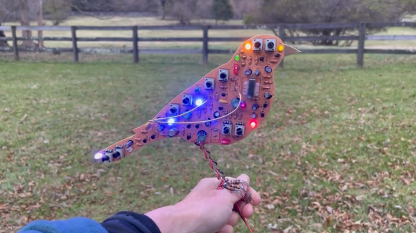
On our favourite low-attention-span content site, [Kelly Heaton] has recently started sharing a series of “Printed Circuit Birds”. These are PCBs shaped like birds, looking like birds and chirping like birds – and they are fully analog! The sound is produced by a network of oscillators feeding into each other, and, once tuned, is hardly distinguishable from the bird songs you might hear outside your window. Care and love was put into making this bird life-like – it perches on Kelly’s arm with legs woven out of single-strand wire and talons made out of THT resistors, in the exact same way you would expect a regular bird to sit on your arm – that is, if you ever get lucky enough. It’s not just one bird – there’s a family of circuit animals, including a goose, a crow and even a cricket.

Why did these animals came to life – metaphorically, but also, literally? There must be more to a non-ordinary project like this, and we asked Kelly about it. These birds are part of her project to explore models of consciousness in ways that we typically don’t employ. Our habit is to approach complex problems in digital domains, but we tend to miss out on elegance and simplicity that analog circuits are capable of. After all, even our conventional understanding of a neural network is a matrix of analog coefficients that we then tune, a primitive imitation of how we assume human brains to work – and it’s this “analog” approach that has lately moved us ever so closer to reproducing “intelligence” in a computer.

Kelly’s work takes a concept that would have many of us get the digital toolkit, and makes it wonderfully life-like using a small bouquet of simple parts. It’s a challenge to our beliefs and approaches, compelling in its grace, urging us to consider and respect analog circuits more when it comes to modelling consciousness and behaviours. If it’s this simple to model sounds and behaviour of a biological organism, a task that’d have us writing DSP and math code to replicate on a microcontroller – what else are we missing from our models?

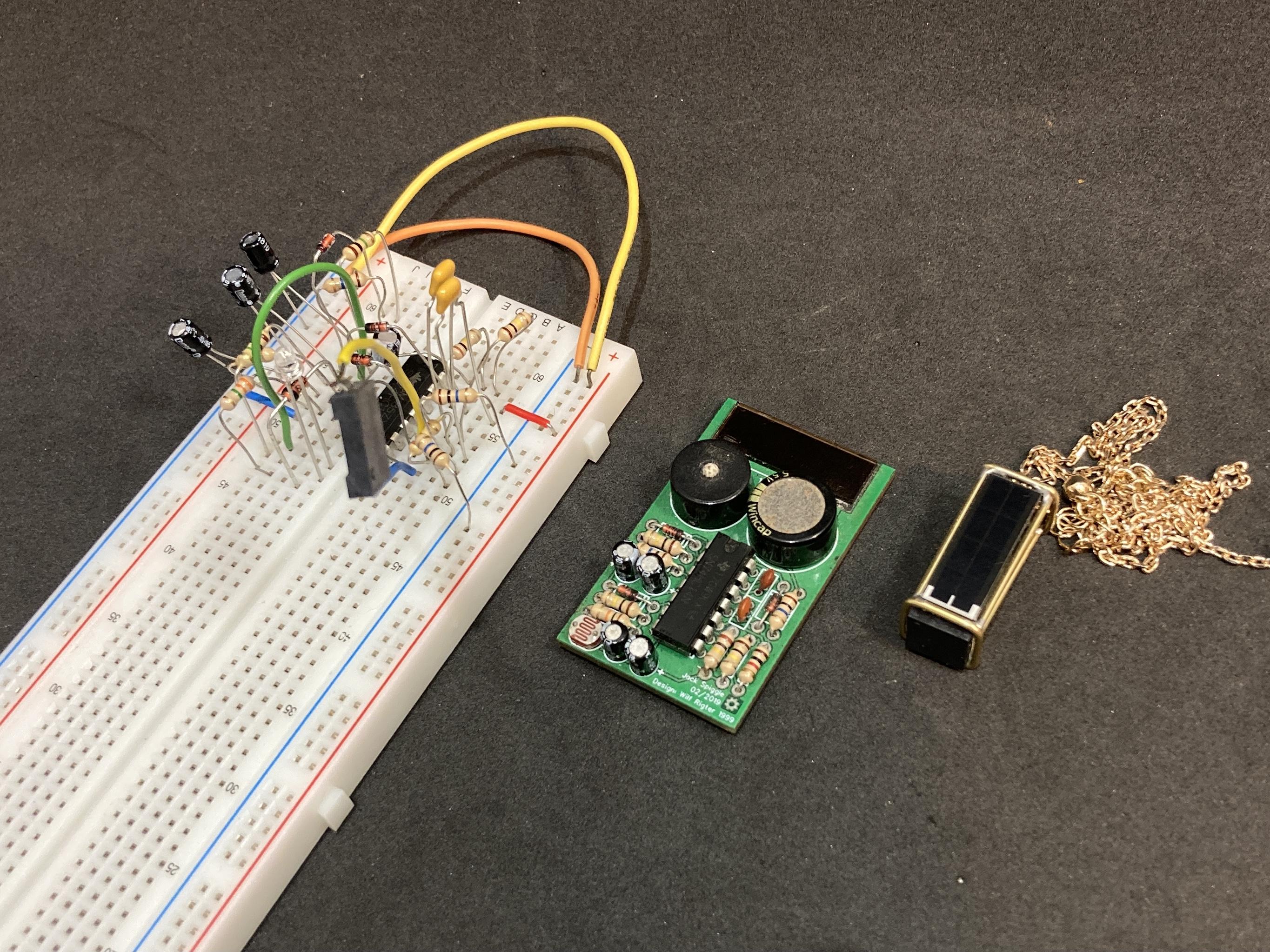
Kelly has more PCBs to arrive soon in preparation for her NYC exhibit in February, and will surely be posting updates on her Twitter page! We’ve covered her work before, and if you haven’t seen it yet, her Supercon 2019 talk on Electronic Naturalism would be a great place to start! Such projects tend to inspire fellow hackers to build other non-conventional projects, and this chirping pendant follows closely in Kelly’s footsteps! The direction of this venture reminds us a lot of BEAM robotics, which we’ve recently reminisced upon as something that’s impacted generations of hackers to look at electronics we create through an entirely different lens.

Continue reading “Printed Circuit Bird Family Calls For Us To Consider Analog”

Solar-powered pendant chirps like a bird.

BEAM Bird Pendant Really Chirps

[NanoRobotGeek] had a single glorious weekend between the end of the term and the start of exams. Did they buy a keg and party it up? No, in fact, quite the opposite — they probably gained a few brain cells by free-form soldering this beautiful chirping bird pendant at 0603 instead.

Three versions of basically the same circuit.The circuit is a standard BEAM project built around a 74HC14, but [NanoRobotGeek] made a few changes to achieve the ideal chirp sound. As you can see in the video after the break, it chirps for around 30 seconds and then shuts off for 1-2 minutes before starting up again.

What is better than a BEAM project? A portable one, we say. Although the chirping would probably get old pretty quickly, there’s just no substitute for working so small that you can carry it around your neck and show it off.

This one is kind of a long time coming, because [NanoRobotGeek] started by breadboarding the circuit and then made a PCB version way back in 2019, which they were attempting to miniaturize with this project. We think they did a fantastic job of it, and the documentation is stellar if you are crazy enough to attempt this one. You will need a lot of blu tack and patience, and pre-tinning is your friend. Be sure to check out the demo after the break.

The name checks out, and this isn’t [NanoRobotGeek]’s first foray into tiny circuit sculpture — just take a look at all we’ve covered.

Continue reading “BEAM Bird Pendant Really Chirps”

Hackaday Podcast 146: Dueling Trackballs, Next Level BEAM Robot, Take Control Of Your Bench, And Green Programming

Postpone your holiday shopping and spend some quality time with editors Mike Szczys and Elliot Williams as they sift through the week in Hackaday. Which programming language is the greenest? How many trackballs can a mouse possibly have? And can a Bluetooth dongle run DOOM? Join us to find out!


Take a look at the links below if you want to follow along, and as always, tell us what you think about this episode in the comments!

Direct download (52 MB)

Continue reading “Hackaday Podcast 146: Dueling Trackballs, Next Level BEAM Robot, Take Control Of Your Bench, And Green Programming”

Light-Tracking BEAM Robot Can See The Light

BEAM robotics, which stands for Biology, Electronics, Aesthetics, and Mechanics, is an ethos that focuses on building robots with simple analog circuits. [NanoRobotGeek] built a great example of the form, creating a light-tracking robot that uses no batteries and no microcontrollers.

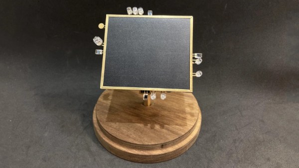
The robot aims to track the brightest source of light it can see. This is achieved by feeding signals from four photodiodes into some analog logic, which then spits out voltages to the two motors that aim the robot, guiding it towards the light. There’s also a sound-detection circuit, which prompts the robot to wiggle when it detects a whistle via an attached microphone.

The entire circuitry is free-formed using brass wire, and the result is an incredibly artful build. Displayed in a bell jar, the build looks like some delicate artifact blending the past and future. Neither steampunk nor cyberpunk, it draws from both with its combination of vintage brass and modern LEDs.

It’s a great build that reminds us of some of the great circuit sculptures we’ve seen lately. Video after the break.

Continue reading “Light-Tracking BEAM Robot Can See The Light”

A tiny solar-powered robot that even works indoors

Tiny BEAM Robot Smiles Big At The Sun

What have you been working on during the Great Chip Shortage? [NanoRobotGeek] has been living up to their handle and building BEAM robots that are smaller than any we’ve seen before. What are BEAM robots, you say? Technically it stands for Biology Electronics Aesthetics and Mechanics, but basically the idea is to mimic the movement of bugs, usually with found components, and often with solar power. Here’s a bunch of tutorials to get you started.

The underbelly of what might be the world's smallest BEAM robot.
This was before the large, flat storage capacitor came and covered everything up.

This here is an example of a photovore or photopopper — it moves toward light using simple logic by charging up a capacitor and employing a voltage monitor to decide when there’s enough to run two tiny vibration motors that make up its legs and feet.

[NanoRobotGeek] started in a great place when they found these 25% efficient monocrystalline solar panels. They will even make the bot move indoors! If you want to build one of these, you can’t beat [NanoRobotGeek]’s guide. Be sure to watch it toddle around in the demo video after the break.

We love to see people work at all different scales. Last time we checked in with [NanoRobotGeek], they had built this solar-powered ball-flinging delight.

Continue reading “Tiny BEAM Robot Smiles Big At The Sun”

Spiffy Summer Project Sources Solar Sounds From Scraps

[Gijs Gieskes] has a long history of producing electronic art and sound contraptions, and his Zonneliedjes (sunsongs) project is certainly an entertaining perpetuation of his sonic creations. With the stated goal of making music from sunlight, the sunsongs most prominent feature is solar panels.

Although It’s not clear how the photons transform into the rhythmic crashes and random beep-boop sounds, the results are quite satisfying. We have a strong suspicion that the same principals that turn random junk into BEAM robots are at work, maybe with some circuit bending sprinkled on for good measure. One detail we were able to glean from a picture of the device he calls “mobile” was a 40106 oscillator, which [Gijs] has used in previous projects.

The construction style that [Gijs] uses reminds us of the “Manhattan” construction style the amateur radio homebrewing community favors. Squares of copper PCB are glued directly to the back of the solar cells and the circuits are built atop them. Looking carefully at the pictures we can also see what look like cutoff leads, suggesting a healthy amount of experimentation to get the desired results, which we can all relate to.

Be sure to check out the video after the break, and also [Gijs] website. He’s been hacking away at projects such as these for a very long time, and we’ve even featured his projects going back more than 15 years. Thanks for the continued hacks, [Gijs]. We look forward to seeing what you come up with next!

If the terms “BEAM robotics” and “circuit bending” are unfamiliar to your ears (or if a refresh is due), be sure to check out our recent re-introduction to BEAM robotics and our classic “Intro to Circuit Bending” to get acquainted. Continue reading “Spiffy Summer Project Sources Solar Sounds From Scraps”