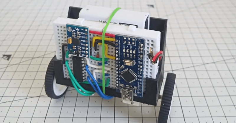
A self-balancing robot isn’t a new idea, but we liked the aesthetics of [Maker ATOM’s] build. The use of a breadboard and a printed bracket looks good, as you can see in the video, below.
Like most first-time projects, though, there were some lessons learned. The power supply needs a little work and the range of balance compliance didn’t meet expectations. But those problems are soluble and, as usual, you often learn more from working through issues like these.
The heart of the system is an MPU6050 which provides a gyroscope and accelerometer along with fusion capability onboard. The availability of libraries for the sensor and the PID controller makes the project pretty simple to finish.
In particular, a PID control loop looks at the desired state of the system and the current state. It then computes an output based on the difference in state at the current time and over time in different ways. In other words, part of the output forms because of the raw difference but other parts of the output form due to accumulated error over time or from sudden perturbations. Adjusting the gains so that these parts stay in balance can be a bit tricky.
However, in the end, the two batteries were not sufficient to power the device adequately. Temporarily, a bench supply did the trick, but the batteries still needed to be there to provide some counterweights for balance. Experimenting wth some PID loop gains might also improve operations.
There are plenty of similar projects to draw inspiration from. The design doesn’t have to be difficult.


I think the reduction gearbox may add slop/backlash that need to be accounted for. And as the article says the PID loop can be tuned and making sure the sensor module has enough resolution and high enough update frequency and low latency. Some pid loop implementations take a lot of processing power making it too slow for real time applications like these.
That’s why they use kalman filter
Ahh a Segway for mice…
Place the axle(s) above the circuit board and batteries.
B^)
Dinky little DC motors are tricky for this application. The gain curve to get them playing ball is almost certainly not symmetrical for forwards and backwards and the chance of being identical between motors at the low torque end of things slim. If they had encoders, then they could be speed controlled rather than torque, and with a closed loop, far easier to accomplish.
All that being said, used to work for a startup, where one of these was built with encoders. Worked fine with conventional control (well the same kit in another robot), but when the AI tried to run it – far wobblier than the torque control above. So very well done. It’s a neat project, works well given the motor choice and whoops an AI.
Not efficient at all, but torque gain curve of motors can be stabilized by putting a resistor in series with them. The larger it is, the more it swamps the back EMF component of the total voltage across motor and resistor. This can lead to spongy response as it will limit the maximum current and thus acceleration of the motor too. In small degrees this might all be good things to explore. A better solution is a full bride operating as a current source rather than a voltage source.
It’s wiggly/high-frequency. Giving it more angular momentum will calm that down. (It’s easier to balance a broomstick on your hand than a pencil.)
Get that battery weight up higher.
But it looks 90% there. Woot.