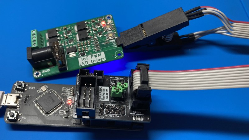
Did you ever struggle with an ESP32 board of yours, wishing you had exposed that UART, or seriously lacking the JTAG port access? If so, you should seriously check out [0xjmux]’s ESP-PROG-Adapter project, because [0xjmux] has put a lot of love and care into making your ESP32 hardware interfacing a breeze. This project shows you how to add JTAG and UART headers with extra low board footprint impact, gives you a KiCad library to do so super quickly, and shares a simple and helpful adapter PCB you can directly use with the exceptionally cheap Espressif’s ESP-Prog dongle you should have bought months ago.
The hardware is perfect for ZIF no-soldering interfacing – first of all, both UART and JTAG can be connected through a SOICBite connection, a solderless connector idea that lets you use SPI flashing clips on specially designed pads at the edge of your board. For the fancy toolkit hackers among us, there’s also a Tag Connect symbol suggested and a connector available, but it carries JTAG that you will already get with the SOICBite, so it’s maybe not worth spending extra money on.
Everything is fully open-source, as one could hope! If you’re doing ESP32 hacking, you simply have to order this board and a SOIC clip to go with it, given just how much trouble [0xjmux]’s board will save you when programming or debugging your ESP32 devices. Now, you don’t strictly need the ESP-Prog dongle – you could remix this into an adapter for the Pi Pico board instead. Oh, and if designing boards with ARM CPUs are your thing, you might benefit from being reminded about the Debug Edge standard!


A completely unrelated quirk on my side, but I love seeing ICDs (in-circuit-debuggers) using the same MCUs inside them as the ones they are meant to be debugging.
Example PICkit having a PIC24, an ST-LINK using an STM32, etc
It just brings me confidence for some reason. Never could rationalise that.
Love making my own development tools. I’ve built many atmega icsp programmers that are just atmega328p’s that program other atmega328p’s. There’s tons of super useful programming jigs and standalone bootloader flashing boards you can make yourself now that small batch pcbs can be had very cheaply and quickly.
The recursive programming thing made me think of https://dicks.home.xs4all.nl/avr/usbtiny/index.html.
I was thinking that was the first USB/AVR programmer based on an AVR, but it points to Igorplug and that OBdev one. How deep does the rabbit hole go?
I have been mulling over an ESP32 project where I wanted as smaller PCB as possible – this looks to be a good and affordable way of programming with a small connector footprint – brilliant.
Had a look through the schematics, GPIO2 is used in the SOICByte UART board footprint – but it doesn’t seem to be used on the programmer side. Does anyone know why it is included?
GPIO2 and GP_PD are used on earlier revisions of ESP8266 boards for programming, and SOICBite passes them through just in case you need them. For ESP32s you don’t need either.
Part of my goal with this was to make it as easy to use as possible – To clarify, I’ll add another example to the adapter schematic for ESP32 usage and will add a table clarifying Pin defs to the README.
If you have any other questions, please don’t hesitate to ask! :)
Magic, thanks very much for the info :)
I like the idea, but it’s missing a key point, IMO.
I prefer to just use modern (most any post-2020) ESP32s that provide serial console and debug print, JTAG, AND actual USB over the two USB pins. Saves the cost and space of an external uart and the two transistors for reset and lets me use a single easy cable for power, jtag, and serial console during development.
The price of a similar capable ESP32-S3 is about the same as an ESP32-nothing plus uart plus transistors + the couple of needed resistors plus connectors. It’s a bonus that you get USB host mode and reasonable target mode to just copy uf2 files for upgrades if you want to go that way, though I rarely do.
I’ll concede that some applications demand a real serial port (which you can still add) and that the newer parts are sometimes missing blocks present in the ESP32-nothings, so check the data sheet before you jump in. 45 GPIOs (with a significant asterisk), the ability to remap pins with a big mux to simplify layout, the slightly faster cores in S2 and S3 (the RISC-V parts so far are all way under 240 Mhz) dedicated GPIO interface, octal SPI at 80 or maybe 120Mhz, better memory handling with fewer goofy restrictions, and other integrated lessons learned from millions of ESP32 sales just make them nicer parts to use in a design.
Hopefully they’ll build a dual-core RISC-V with ALL the features at the same time at way above 240+Mhz, integrated DRAM, all the radios, and keep that $3 hobbyist -friendly point. That would be sweet! So far, they keep building a different 80% of the perfect part.
Not mentioned but important to the success of clipping on the edge of a 1.6mm PCB, the SOIC clip needs to be modified: https://github.com/SimonMerrett/SOICbite/blob/master/HOWTO_mod_clip.md