It’s not too hard to make your electronics project get warm. Design your traces too small, accidentally short the battery inputs together, maybe reverse the voltage going to your MCU. We’ve all cooked a part or two over the years. But what about making a PCB that gets hot on purpose? That’s exactly what [Carl Bugeja] did in his second revision of a PCB hot plate, designed to reflow other PCBs.
[Carl’s] first attempt at making a hot plate yielded lukewarm results. The board, which was a single snaking trace on the top of an aluminum substrate, did heat up as it was supposed to. However, the thin substrate led to the hot plate massively warping as it heated up, reducing the contact against the boards being soldered. On top of that, the resistance was much greater than expected, resulting in much lower heat output.
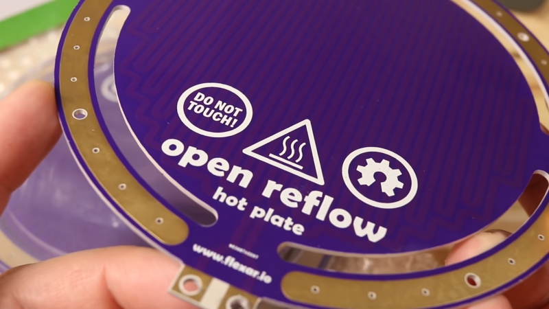
The new revision of the board is on a thicker substrate with much thicker traces, reducing the resistance from 36 ohms on the previous design to just 1 ohm. The thicker substrate, paired with a newer design with fewer slots, made for a much sturdier surface that did not bend as it was heated.
We especially like the wiring solution [Paul] came up with for his new hot plate. Soldering to a resistive heater can be a massive annoyance since the board will act as a heatsink. While Alligator clips do work for testing, there is always the chance of them slipping and shorting against each other. [Paul] decided to make a custom flexible PCB that would connect with nylon screws to the hot plate, and fit directly onto the connection points of his power supply.
Unfortunately, this new revision of the board did have some issues as well. The biggest of these was that there was a miscommunication with the board manufacturer, and the solder mask used begins to degrade after a few hours at the operating temperature. But for light-duty work and intermittent use, it is the perfect tool.
You can read more about [Paul’s] first PCB hot plate in our previous coverage of it here.


I could see this working well on an aluminum substrate with high-temperature dielectric
Alternatively, buy a ceramic hotplate. The ones we use at work are capable of going up to 1000F and will hold that temp all day long without issue. Something used on eBay would probably be your best bet. The one everyone seems to use in the industry including where I work, the HP130915, goes for north of $400 new.
I applaud the effort he put into making his own. While imperfect is certainly did the job in the end. Though I can’t see it being terribly useful unless you really need a thin heating element for some project.
Considering the size of the PCB, it seems it would be cheaper to just buy reflow oven! /s
Why…? Those things are like $15 for 5 of ’em.
But how much is the power supply….
HOWEVER – 12V @12A is readily available from your car battery, so budget reflowing could happen in the garage with a couple of jump leads.
12Vac is pretty cheap too. One transformer.
Seeing that they’re purple I’m guessing they came from OSH Park. Have you seen their prices? I got a quote for a 95mmx75mm board and it was $56.27 USD for TWO!
I ended up going with Seeed Studio who I’ve used in the past and got 10 boards for under $30 shipped. And I can get them in almost any color I want, not just purple.
pcbway. not oshpark
or jlcpcb. of of them chinese ones; cheapo yet decent quality
For small designs I found OSH park to be great … I never payed more than USD 10 for my boards and that includes shipping to Germany. But the boards I design are very small, most of them smaller than a square inch with a lot of tiny SMD parts on there.
Would make a great preheat (@ ~ 100 deg C ) for hot air rework and hopefully that temp would not have adverse effect on the heaters solder mask.
Nice job!
I don’t know about modern electric stoves (ranges), but General Electric Calrod™ heating elements for cooking pans could be salvaged; when new, their top surfaces were flat(ish) to make good contact with flat pan bottoms. An Al plate would spread the heat.
As probably almost everyone kn:ows, these can get orange–yellow hot, but that’s probably when fed with 240 V (in the USA).
Problem could be their low resistance, but a high–current triac duty–cycle control (15 A rated) on 120 V should do fine, at a guess.
•=•=•=•
Regarding alligator clips shorting, at least their insulating boots should extend right to their tips.
That reminds me I was on holiday recently with no tools and had to fix something electrical.
I used the electric cooker ring to melt some solder out of the bottom contacts of an old filament light bulb (so old, that it was leaded, which helped), and then used the blob of molten solder to do the bodge-up.
Been keeping track of the progress he’s been making on this project and seen the video the day he posted it. Can’t wait to see v3 I really think he’s going to nail it.
Carl has egg on the face of his project….and me thinks that’s cool..err…hot!
Been there, tried that. AliExpress has off-the-shelf aluminum heat plates for led bulb repair. The problem is that fr4 is a very good heat insulator and it’s very hard to achieve the required temperature at the top by hearing the bottom. You’ll have high temperature wherever you have huge poligons and a lot of vias and too low everywhere else. In the end I just invested in a toaster oven. A proven method for reflow ;)
May be without solder mask at all and putting some kapton tape over the pcb it can be more durable.
Why not AC powered with PID? Wouldn’t need a $1000 PSU.
I already used an inverted (old) clothes iron for that purpose. At least this is designed to reach 200°C. A normal cooking range would also do the job. Except of course a gas fired one :-)
A trick for gas stoves is to fill a pan with sand. I’ve seen that once or twice on HaD and it works decently, especially if you use a temp probe or IR temp gun.
The temptation would be to incorporate a few thermistors into the board and have some temperature feedback or control loop rather than just dialing in a voltage and keeping your fingers crossed. This reminds me of the heat mats for terrainiums or antifog wing mirrors. Although I doubt they’d safely get up to reflow temperatures if mistreated enough.
Who is [Paul]? Did this article get copy pasta’d wrong? Regex failed? Suddenly you’ve decided Carl needs a name change?
Thanks for the feedback, Jack. Paul is Carl’s alter ego :)
Why not build this feature into one of the layers of the board you are building? Automatic reflow or self destruction, depending on the need.
Is there a reason one would chose building a hotplate over a reflow oven?
When I’ve seen people doing it using a waffle or clothes iron, etc I assume that the advantage is price and maybe they already had that lying around. But if one is going to work this hard wouldn’t a thrift-shop toaster oven + a thermocouple, SSR and Arduino clone from any o’l China shop get a better result for a lot less effort and not that much money?
I’m not trying to be mean. I actually hope someone has a good answer that I can learn from.
A hotplate is only 2D, and therefore much more compact than a 3D oven. Smaller is better in a crowded space. :-)
I would just use an electric skillet.
This is a very *expensive disposable* reflow heater that doesn’t last a long time.
Heat conduction is not perfect, so there is a delta T. In order to reflow a PCB, the heater have to be quite a bit reflow temperature.
FR4 (commonly 120C(regular) – 180C(high Tg)) are only rated for short exposure to reflow temperature. When it is above glass point and delamination, discoloration etc.
The heater uses an aluminum base, not FR4. The heated FR4 boards only have short exposure.