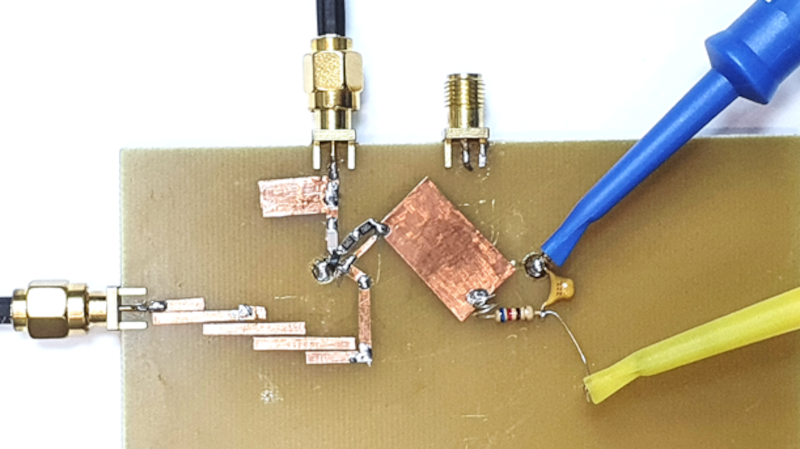
It is an age-old problem. You have a 2.5 GHz source and you want it at 5 GHz. You need a frequency doubler. [All Electronics Channel] has an interesting video that talks not only about the theory of such a device but shows a practical one made with copper strips on a blank PCB substrate.
A fun thing about microwaves is that even little strips of copper are circuit elements since the wavelength at 2.5 GHz is only 12cm. That means a quarter-wave stub is only 3 cm — just over an inch.
The construction technique used is simple and, as he points out, experimenting with a real circuit will give you much more feel for how these circuits work than just reading and working out the math.
The multiplier drives an amplifier into nonlinearity which, of course, generates harmonics. Then a bandpass filter selects the second harmonic. If you haven’t dealt with stub circuits before, you might want to read up on how a piece of copper connected at one end can act like an inductor, a capacitor, or even a tuned circuit.
If you want more detail on the copper tape technique, we can help. If you don’t want to double frequency, maybe you would prefer to try voltage.


Interesting… RF Copper tape magic is the best!
Cool! Look at this great video about Distortion that he made! https://youtu.be/acWZLW5EE3U
“… the wavelength at 2.5 GHz is only 12cm”
That’s a free space wavelength. The wavelength in PCB material is much smaller than that (divide by sqrt(epsilon_r)).
N.B. Microstrip (like this board) has E field in both the PCB dielectric and air.
Excellent info. Thank you, I was wondering about that myself, but didn’t know the math.
Looks like magic to me. Clearly I need to learn more about HFRF.
it is :P
I always think that when seeing such a system set up too, its such an interesting thing, same with pure analogue BEAM electrics too – so much magic in how they work that isn’t obvious if all you have done is spend time in more ‘normal’ digital electronics worlds…
Seems like he is a great presenter, but I have to admit I struggled to follow his accent at times… The tuning of the system just by adding copper tape is really elegant and so simple, really like the suggested method too – playing around in the real world is often such a good method for developing a real understanding.
I work in a lab that deals with SRF circuits (superconducting radio frequency) and I can say that the field of rf is a mix of black magic and a dizzying amount of mathematics. What I work on isnt a very complicated rf circuit (can’t really go into detail on exactly what I work on, but it’s not anything complex by any stretch of the imagination) and we STILL end up doing an insane amount of math to verify even a tiny change, and even then sometimes something works/works differently than it should without any of us knowing exactly why.
I really like this empirical approach, esp with circuits like these where there are so many X factors that accounting for all of them would drive you crazy. (Which way is the FR4 weave laid out?)
But it also relies on having good instruments. You can’t tweak what you can’t see.
With the NanoVNA type devices, though, you’re pretty good up to 2.4 GHz.
But up to 6 GHz gets tricky. The only thing I’ve found is the GS320. Anyone know anything about these?
For about $400 one can pick up a dual-port VNA rc2 LibreVNA for 100kHz – 6GHz
https://github.com/jankae/LibreVNA
https://www.aliexpress.com/item/1005002428364525.html
It is an interesting project that could use some more community input. For the price, it is a fine pre-built kit for this band. And while it is far from perfect, it is intended for amateur users to mod as needed, and about ten times less expensive than the equivalent options.
I am interested in the harmonic mixing modes this unit can achieve, but it still needs a lot more work.
Cheers,
VE7NTP
Quite nice to see a compatriot of mine featured here. Thank you Al for the article. There’s also a good video he did a while back, thou this oe released just in portuguese, about a inductor tester he produced to measure saturation curent for inductors and transformers, using a BIG capacitor as a voltage source with huge current output capability.
But I think the most important question must be, will this make my popcorn twice as fast?
interesting
Not sure if you want to tread into the 5Ghz spectrum unregulated since radars also operate on this range. The reason why WiFI need to have DFS in order to get licensed to operate in 5Ghz…