FR4 is FR4, right? For a lot of PCB designs, the answer is yes — the particular characteristics of the substrate material don’t impact your design in any major way. But things get a little weird up in the microwave range, and having one of these easy methods to measure the dielectric properties of your PCB substrate can be pretty handy.
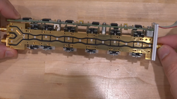
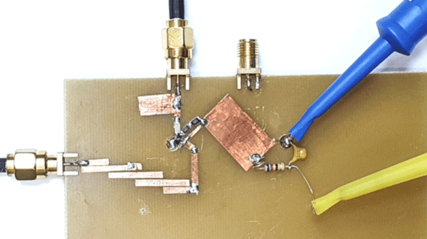
The RF reverse-engineering methods [Gregory F. Gusberti] are deceptively simple, even if they require some fancy test equipment. But if you’re designing circuits with features like microstrip filters where the permittivity of the substrate would matter, chances are pretty good you already have access to such gear. The first method uses a ring resonator, which is just a PCB with a circular microstrip of known circumference. Microstrip feedlines approach but don’t quite attach to the ring, leaving a tiny coupling gap. SMA connectors on the feedline connect the resonator to a microwave vector network analyzer in S21 mode. The resonant frequencies show up as peaks on the VNA, and can be used to calculate the effective permittivity of the substrate.
Method two is similar in that it measures in the frequency domain, but uses a pair of microstrip stubs of different lengths. The delta between the lengths is used to cancel out the effect of the SMA connectors, and the phase delay difference is used to calculate the effective permittivity. The last method is a time domain measurement using a single microstrip with a couple of wider areas. A fast pulse sent into this circuit will partially reflect off these impedance discontinuities; the time delay between the reflections is directly related to the propagation speed of the wave in the substrate, which allows you to calculate its effective permittivity.
One key takeaway for us is the concept of effective permittivity, which considers the whole environment of the stripline, including the air above the traces. We’d imagine that if there had been any resist or silkscreen near the traces it would change the permittivity, too, making measurements like these all the more important.
Continue reading “PCB Dielectric Constant Measurements, Three Ways”