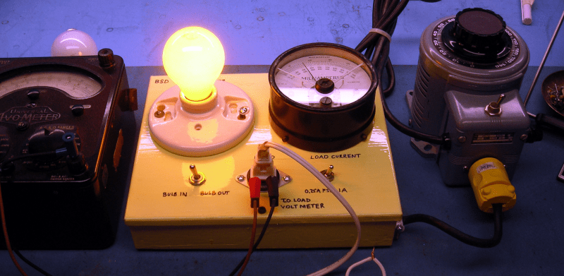
If you work on old equipment, you know that there’s always that tense moment when you first plug it in and turn it on. No matter how careful you have been, there’s some chance your garage sale find is going to go up in smoke. [BasinStreetDesign] built a little box that can help. On one side is a variac and the device you want to test goes into the other side.
In the middle? A lightbulb, a few switches, and a meter to monitor the current. The magic happens because the lightbulb will stay relatively cool and only light dimly if the device under test is drawing an appropriate amount of current. You match the bulb wattage with the approximate watts you expect the load to draw. If the device’s power is shorted to ground, though, the bulb will light brightly and this causes the lightbulb’s resistance to increase, thus helping to protect the device.
Of course, this is an old idea but we liked the construction method and the inclusion of a variac. The ammeter is great, and there is a connection for an external voltmeter that has some short-circuit protection. We might have opted for a second built-in voltmeter. The analog meters add to the old-school ambiance, but digital meters could be interesting and are easy to find these days.
Be sure you match the lightbulb wattage to your load. If the bulb is too small, it will light anyway. Think of it as a voltage divider. If the bulb is too small, it will have a higher resistance than the radio and get most of the voltage across it, leaving very little for the test device. If it is a higher-wattage bulb, it will have a lower resistance and the radio will take most of the voltage. In either case, the current through will depend on both resistors. If the radio is shorted, or nearly so, its resistance will be close to zero and that’s why the bulb will light brightly.
If you want a more classic build along with suggested test procedures and tips, there’s a good article over on antiqueradio.org. If you do decide to go with digital displays, consider a steam punk aesthetic like [Christine’s] radio project. Or, you could overengineer the variable transformer.


Answers the question of “what do I do with all these incandescents? ”
I”ve used small ones for regulating the charging current on batteries.
Where does one buy an incandescent bulb at all these days? They’re banned.
Really only regular consumer grade household bulbs are off the menu. Look for “rough service” bulbs – they are still made. They are a little more expensive, but you get a better bulb.
Have tried, but can’t find any. They -say- you can buy them, but no store stocks them.
I was going to suggest a Garage Door Opener bulb, but come to think of it, the last one I bought was LED.
Oven light bulbs
Decorative bulbs (tho those quickly went LED)
Amazon
Stores can sell special exempt versions but now there’s so little demand.
Also they weren’t banned per se just required to have a certain efficiency ratio.
Practical and functional. I bet it isn’t novel but I would call this a 100% certified Hackaday quality hack.
Good Hackkeeping Seal of Approval!
I would absolutely buy a shirt with the oval logo and this text.
I don’t really go in for that sort of thing, and I would too…
No it’s not new, they had something like that in the TV repair shop I worked in as a teen in the 1960’s. The owner used to call using it “the 60 cycle smoke test”
We always said you could fix any tv with a cheater, a heater, and a beater. That is, a cheater cord, a soldering iron, and a hammer.
Love it!
(we didn’t have that saying in the TV shop where I worked)
Same here, that’s where I learned the technique and subsequently made a fixture with an inline fuse, power switch, bulb socket, and another switch to bypass the bulb for full power. Really helpful for troubleshooting high-power switching supplies, and seeing if the supply’s kickstart circuit is firing into a dead short (bulb flaskes like a strobe).
IIRC, the light bulb was recommended for the RCA/GE TVs that developed shorted flyback transformers.
The Horizontal Output Transistor (HOT!) was shorted, and if you didn’t use the light bulb, you blew another. (After a while, you just knew to replace the flyback as well as the HOT (there might have been a fuse or clamping diode to replace as well).) As a result of the costly lesson, a subsequent chassis family was nearly bullet-proof.
Sam Goldwasser maybe has a Service Tip relating to the light bulb test.
This is similar to the protection that can be applied to servos in case of stalling and lock-up.
It was always a bit weird to see a control system card cage with a dozen 12V car lamps on the front edges of the servo driver boards.
Going way back: In the days before homes had circuit breakers, there were fuseboxes, and the base of a typical 10-20A fuse was the same as a lightbulb. So if a fuse blew, you screwed a lightbulb into the socket. Then as long as the bulb in the fusebox was lit, you still knew there was still a short on that circuit.
Interesting history! Thanks for sharing.
And when the fire starts you run outside and pull the meter off its socket?
Thanks for that! I grew up with those fuse panels in the houses we lived in and I knew the fuse sockets were the same as incandescent bulb sockets, but I never knew that using bulbs in them for troubleshooting was a thing. In retrospect I should have known though – I used the series bulb trick many times (without the variac) when I was servicing motor drivers for fitness treadmills. The light bulbs saved many a mosfet and many an IGBT module. I even used Christmas bulbs in series with the supply line to protect the SSR’s on the boards that drove the incline motors.
I grew up in an older part of town where many of the houses still had fuse panels. If you didn’t have the right amperage fuse then you took the fuse out and put a penny underneath. When you get the chance you buy the right fuse and replace it. One home in the hood burnt down and the fire investigation revealed pennies under every fuse. This was supossed to be a temporary fix.
Guess that was a case of penny wise, pound folish.
My house was build in 1923 and still uses an Edison base subpanel. So long as replacement fuses are available I see no reason to replace the ceramic brick without moving parts to burn/jam.
This jiuse was built in 1923 too. We finally changed to a new panel, with circuit breakers, sometime within ten years ago.
Of course, it wasn’t the original panel replaced.
The house I grew up in had a number of fuse boxes clustered on the wall of the utility room.
One day when Mom was washing clothes, a fuse blew. I saw her take the fuse out and throw it in the waste basket.
Picking it out of the waste basket, I asked her why she did that. “Because it’s bad!” I was around 5 y.o. at the time.
I didn’t notice at the time she replaced the blown one.
So, the next day, while Mom was taking her nap, I climbed up on the washing machine (wringer type) and removed ALL those bad things!
For some reason when I woke Mom up and showed her what I’d done, she wasn’t happy at all!
(One of Life’s Little Lessons [TM] that got me interested in electricity/electronics)
I have a box made by Tektronix for internal use that is essentially the same thing. It has a Variac, ammeter, voltmeter, and four different light bulbs in power-of-two relationships that you can switch in and out of the circuit. So you can pretty much use it to test various loads over a 16:1 ratio.
Thanks for pointing out wattage matching!
This scheme was used when electrolytic capacitors in power supplies had lost the insulating capability of their oxide films. Because such films must have been formed after the caps. were made by applying limited current, applying limited voltage and thus current allowed the films to be re–formed. No experience, only cead about this, but you’d start quite low, and slowly increase the voltage, and menitor the current.
If the elechrolyte had dried out, no luck.
Applying power after a device hasn’t been operated for years/decades is not kind.
I came across an automated rig (forgotten in a back-room) for doing exactly this – from when IT equipment had capacitors the size of paint cans in them. The whole thing was operated by electro-mechanical timers.
Sadly, the six 10,000uF 100V capacitors in the power supply had lost their oxide layers.
Eventually you’ll be limited to 40W oven bulbs. They’ll never get a LED bulb to hold up in an oven, fridge no problem.
I just put together one tester sans bulb to check fuse blowing in a multi-winding power supply in an organ. The bipolar 12V supply to be specific. I was able to ramp up and see the current of one fuse path going all most to the rating then fluctuate and eventually settle down. Now it’s OK but needs monitoring, not fixed.
Could the 7812 or the 7912 regs be shorting, instead of something on a board full of op-amps? There were a few pops and bangs.
78xx and 79xx regulators have a limited life span when used close to their rated currents. Older devices are especially susceptible to spontaneous breakdowns as they often lack some of the internal protections available in newer versions.
When these fail, the failure can be one of two modes:
* Short circuit of either side of the regulator to ground;
* Short circuit across the regulator input and output terminals;
The second failure mode is the most dangerous, as it results in the full supply voltage and current to be applied to the supplied circuit – resulting in catastrophic failure and massive releases of blue smoke. I have only seen this happen with older, cheap, unbranded regulators, but this is not to say that it couldn’t happen with branded devices.
I have a very similar setup – even down to the lovely AVO 8 – but I aso use an isolation transformer for working on old “hot chassis” equipment – the variac alone does not provide such isolation.
Caution: this is dangerous with SMPSs inside equipment.
Such SMPSs are constant power output devices. If you decrease the input voltage, they will attempt to draw more input current. The switching transistors may respond “poorly” to that,
But it’s still a legitimate diagnostic tool especially for SMPSs. http://www.repairfaq.org/sam/smpsfaq.htm#smpstslbt
unless you use a very undersized bulb, it’s just a lazier version of a PTC thermistor many SMPSs already have…while it might kill the switching transistor(s), it will do so in a civilized manner, no fireworks or collateral damage.
It’s not ‘lazier’ at all, unless you’re talking about the ‘laziness’ of the incandescent bulb. The bulb provides a much softer start than the PTC’s you’re talking about, and its resistance starts rising at a lower current than that of the PTC thermistor that would be in an SMPS. The bulb can actually prevent the death of the output devices – the PTC probably won’t do that.
If you are referring to the component that limits AC mains inrush current during turn-on, then there is no PTC thermistor used in AC inputs
But there are NTCs that are used for this.
Have a look at mine: https://hackaday.io/project/174318-current-limiting-isolation-transformer
Hackaday,
It wouldn’t hurt to mention in the article (for the benefit of absolute newcomers) that these bulbs must be *incandescent;* not LED or CFL – and you know someboy’s going to use one and then complain that it doesn’t work.
On one hand I technically agree with you but on the other anyone who ever thinks about using a non-incandescent light in this circuit should keep away from electronics forever (at least with line voltage).
I think I first saw this technique on the excellent YouTube channel Mr. Carlson’s Lab.
A variation of this is used as a speaker protection for pro audio. Especially for tweeter protection.
Oooh! I wish I had thought of that ~40 years ago with a Fender guitar amp that blew the speaker during warmup!
Nothing new, my setup is a little neat. I have four bulbs, two 60watt and two 40watt. With some switches I can select from 40watts to 200watts. I also have a isolation transformer in the mix along with a Variac and a killawatt meter.
Hey!! That’s my thing! It’s here:
https://imgur.com/gallery/JSZVOaB
It’s really weird when you do these things for years and hardly anybody notices or comments on places such as EEVBlog, reddit, antiqueradios.com, etc and then, without warning it hits Hackaday.com. So thank you for that and if anybody wants to ask me a question you can leave a comment at the above imgur link or at reddit at
https://www.reddit.com/r/diytubes/comments/qd1uch/dim_bulb_tester_for_restoring_old_radios_etc/
When I changed my light bulbs to low energy bulbs I kept the old filament bulbs in case they came in usefully so built the in rush current limiter and used a bulb I kept don’t throw anything away