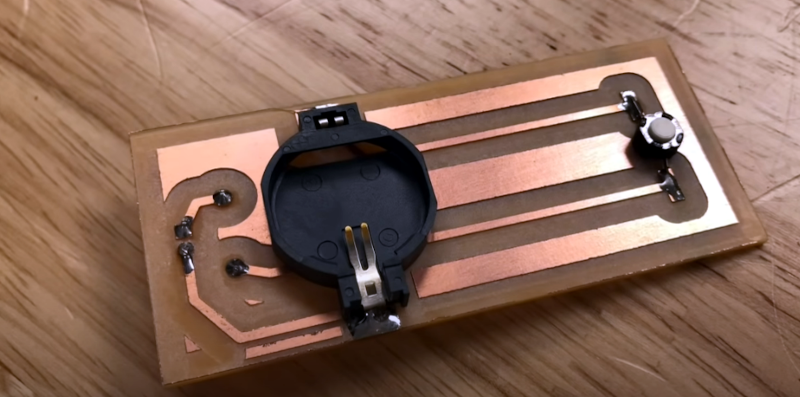
Inspired by his CNC’s leveling system, [Chuck] built a small PCB to help level his 3D printer and he shares the details in the video you can see below. The idea is simple, the nozzle pushes down on the PCB which has a tact switch underneath. When the switch closes, an LED lights.
In practice, you measure the height of the board and use that for your Z offset, and you are done. Our only concern would be how repeatable the switch is. Granted, most people use a piece of paper and that’s probably not totally repeatable or accurate either. Proper feeler gauges are the “right” way to do it, but we know only a few people who do that.
If you ever look into the repeatability of various Z probes like the proximity sensors or the little pins that drop out of a 3D Touch probe, they aren’t that repeatable. Some people use microswitches, too, which is pretty similar to this approach and is apparently good enough.
The board is available, but it is simple enough that you could create it — or an equivalent — with just about any method you use for your PCBs. [Chuck’s] prototype board was milled. We are always surprised more people don’t use the nozzle itself to sense the bed. Some people go to a lot more trouble than just electrical contact even for CNC.


A cheap fully automated clone probe costs less than 10 €.
To me automatic bed leveling was really a game changer.
yeah, not seeing the point of this when you can automate it easily.
I bought one of those and put it on my new printer which was working wonderfully before I put the clone probe on it. It immediately started driving itself as far into my bed as it could. Once I got it to stop trying to destroy my printer, it absolutely refused to do a proper level. Nothing would print until I removed it. Then it took more calibrating to get it working properly again than it did when I first took it out of the box and assembled it.
They’re cheap, and they might work for some, but they’re not game changers, unless you consider having a 3D printer that can’t print to be a game changer, which I suppose it is in an inadvertent way.
I like my piece of paper better. It’s faster, more reliable, and doesn’t run itself before every single print.
Yeah, I left my original Z-Axis limit switch connected on my Ender 3. Even with my BLTouch operational, if you press the switch the Z-Axis comes to a halt. Saves the day and my glass bed on the incredibly rare occasion the BLTouch doesn’t detect the bed.
Ok! I must definitely build this and try it out to level my bed.
You’ll sleep better at night. :-)
The intent of a go/no switch here is admirable. Feeler gauges require a bit of practice to use properly, but even a novice will have more repeatable results than what a microswitch can provide. There’s easily a 0.01″ tolerance or worse in microswitches.
That is simply not true. They repeat to 0.01mm all day. For a printer drivetrain thats as good as you can get.
Ed Nisley, who writes for circuit cellar, wrote this:
https://softsolder.com/2010/04/17/ugliest-tool-length-probe-switch-repeatability/
about adding a tool length probe to his cnc milling machine.
He was finding repeatability better than his cnc mill could manage, with 10 micron repeatability with a cheap microswitch, after a pretty good set of tests.
Great idea and good explaination (on using the Z offset)
But, what I was always wondering … Wouldn‘t it be possible to use a simple digital letter scale or pocket scale?
What I don’t understand is, why don’t people make the beds conductive, then simply pass a current through the head and by adding some servos to the bed adjustments, it can level itself.
I asked myself the same question an 1/2 hour ago. That should actually be possible somehow.
A big problem is the plastic creating an insulating layer. Another is the conductive surface not being a good printing surface. Both can be overcome, but the compromises probably don’t balance out well with the benefits vs other methods.
Technically you don’t need to make the entire build area conducive, you only need the outer edge or even just the corners to be conductive. Perhaps you could even just mount a bendy needle or better yet, a pogo pin, to the hot end and use that to make contact instead of gently slamming the hot end itself onto the bed.
I tried this while working at ultimaker, and indeed plastic buildup caused it to fail very frequently. Even tiny amounts would cause incorrect levels or a failure to detect.
In fact, that’s why I level the printer bed with hot nozzle and retracting the filament a bit, than cleaning. Also, I level the heated bed.
Another fun thing we learned. The glass of your bed changes shape. So any leveling you do to get it “just right” is counteracted by the bed heating up.
And it’s not just heating up, it takes 30 minutes before the glass is “settled” in it’s new shape when heated up. So for the most accurate result, you would need to heat up the bed, wait 30 minutes, and then level it. (But nobody is going to wait for that)
Do people really level cold beds and nozzles? I honestly thought that was obvious. The nozzle and the bed expand when heated, so if you’re dialed in at 0.1mm at 20 degrees C, you’re not at 0.1mm at 200 degrees C. I will admit that I don’t wait 30 mins though, maybe 10 mins. However, my glass surface is pretty thin and bed are isn’t that large so I don’t think it’s an issue.
What about capacitive touch levelling?
@Sandro its not that bad in many printers, a good level while cold is probably good enough when hot… Sure its not ideal, but if it works well enough why worry, and it will on many printers for most common (cooler) filaments – also much easier to do safely – no chance of burns if nothing is hot…
This said as somebody who generally prints ABS and does hot level that printer..
Lulzbot did use this – 4 metal disks at the corners of the bed. Requires the nozzle to be clean from plastic debris also did not work well for large beds that sag in the middle. The hotend body is aluminium and electric contact is not easy.
Our luzbot destroyed the bed when the nozzle cable came loose and lost contact with the hotend.
A few reasons:
1. In your idea, both the nozzle and the bed needs to be electrically isolated from the rest of the system, which might be difficult depending on the design, as these are metal parts that might be grounded through the chassis, via fasteners and stuff
2. Inductive probes exists (and so do contact probes libe BLTouch), which eliminates the need for exposed metal beds. Exposed metal is prone to getting dirty, which is also true for the nozzle
3. Metal beds are inferior to almost anything else available. Personally I’m using textured glass.
You also don’t need servos to do the bed adjustment, you can simply tell the z axis to move a fraction of a millimeter up or down depending on where you are on the bed. More powerful printer circuitry can “mesh level” with this technique. (and by more powerful, it’s simply a probe plus a 32-bit microcontroller instead of 8-bit, so probably only costs $20 more)
Right now, for bed slinger designs, the industry has already settled on either inductive or touch probes. For non-bed-slinging designs, you literally don’t need to re-level your bed for years at a time, or you level-as-you-print.
This hackaday post shows a creative way to solve an non-issue, and I suspect that PCB fabricator gave the guy some discounts for posting this video. They always have those promotions.
Back in 2010, this device would’ve been ground breaking.
The biggest problem with using electrical conduction through the nozzle and bed to detect the bed surface is that any plastic on the nozzle prevents detection leading to the extruder cashing into the bed. Since a hot nozzle usually oozes filament just sitting there, this will be the case most of the time.
As for mesh leveling requiring a 32-bit micro, well the Prusa i3 Mk1 and Mk2 both have mesh leveling and use 8-bit micros.
I don’t understand what this kind of Z leveling is for. Why is a normal induction probe not enough? And since he is trying to replace induction probe with a button is he also using the button for X and Y calibration somehow?!
i don’t understand “normal induction probe” and i feel like maybe i wish i did? i don’t know how it would work, since there’s no metal in my bed?
Induction probes are used with aluminum heated beds to detect height, but if you have a glass bed you can use a capacitive probe, will detect it just fine
It’s for bed slinger designs, specifically, the printer shown in the video is an Ender 3, which is a $200 printer with all corners cut and zero bells and zero whistles. You can add an induction probe but you’d need to muck with its firmware.
Yeah–many (perhaps even most) 3D printers in consumer’s hands don’t have inductive bed probes.
Unless your bed is warped, mesh leveling is not really doing anything.
Automatic bed leveling is doing only minimally more and nothing worth writing home about.
Tramming your bed is simple.
1. Home the printer
2. Raise the z axis to the thickness of whatever you are putting between the nozzle and the bed.
3. POWER OFF THE PRINTER
4. Get your interference fit between the nozzle and the bed all over. Adjust it again if you have to.
5. Power on, home the printer and hit go.
Why does this work? Your printer believes it is at Z0 when it begins printing. If you had paper between the nozzle and the bed when you went around checking things, it is going to be offset by around .1mm.
If your layer height is .2mm, that is an error of 50%.
i don’t get it. i always G28 my printer on start-up, so it re-calibrates off of its limit switches. do you really just let your printer assume it’s at Z0 on power up? kind of neat that you could get it to work at all like that, really!
and of course you’re right that you have to account for the height of the paper when levelling. i mostly use 0.2mm layer height, and indeed about an 0.1mm piece of paper, just like you say, and i typically calibrate it so that the bottom layer is somewhat smooshed (i.e., it’s printing 0.2mm of plastic into an 0.1mm gap). i do that on purpose for base layer adhesion purposes. i adjusted my calibration procedure until i came up with something that had this quality, i didn’t just use it however it happened to be and then not pay attention to how it prints…
anyways, i have a delta, is why i care for mesh levelling. there’s a slight spherical distortion from the rods not quite being the same length as the delta kinematic software thinks they are, and it’s slightly off-center (astigmatic?) because the rods aren’t all exactly the same length, and probably a few other kinds of repeatable slop i haven’t figured out how to think about yet. it’s about 0.5mm over the whole print area, or less than 0.1mm per mesh grid cell with the marlin mesh leveling i’m using. i could probably have manually tuned it slightly better than that, but mesh leveling takes care of it in a pretty generic way that is easy to maintain as the printer suffers mechanical wear and the layers of tape on the bed come and go and so on. after 6 months or so, there tends to be a noticable high corner with poor adhesion, and i have to re-do it, though honestly i don’t know why.
>i don’t get it. i always G28 my printer on start-up, so it re-calibrates off of its limit switches. do you really just let your printer assume it’s at Z0 on power up? kind of neat that you could get it to work at all like that, really!
Yeah, that is exactly how it works. The reason why you are using paper is so that the hotend is not interfering directly with the bed (READ: Crashing).
The printer WANTS to be at a state where Z0 really means Z0. Not Z0 + whatever I stuck between the nozzle and the bed.
I can see a slight benefit if you are still running a delta, but isn’t that just one more reason to move away from a delta? If I had to tune each “leg” of the printer, I would RUN.
The one thing I have yet to deal with is putting tape, glue, or hairspray on my bed. PLA will stick like magic to clean glass. If you have a chamber, ABS will do the same.
the printer wants no such thing! i want to have good first layer adhesion, preferably with a minimum of squishing-out (my first layer is wider dimensionally than subsequent layers). my desires drive the tuning process, which inevitably features some trade offs. whether i tune the printer to a geometric ideal or not, it doesn’t change the fact that i’m gonna have to pay attention to the result and decide how i want to adjust it.
but i mean there’s no question, the thickness of the paper does have to be taken into account one way or the other, and also some subjective assessment is involved in gauging the proximity to the paper. that’s why i have a passing interest in automatic or assisted probing.
i still feel very good about the reasons i chose delta. all 3 of my axes are symmetric (nominally), and they’re all belt drive (no lead screws). there are a variety of issues that seem inevitable with most of the common cartesian designs and i wanted to avoid them, and i successfully did avoid them. i’m not saying one is better than the other, but i made my bed and found it quite comfortable. people who learn to maintain their cartesian printers surely find them quite satisfactory as well!
i certainly do not tune each leg of the printer! the one simple process of mesh leveling is the only tuning i do since setting the thing up in 2014. during assembly, i tuned the legs by assembling all 6 of them the same time and using a simple jig to keep them all the same length. it’s not perfect, but it was pretty trivial to do.
thanks for the tip about clean glass! it’s something i think about sometimes. i’ve got an acrylic build plate at the moment so i have to use tape. but the most recent batch of blue painter’s tape sticks to the PLA so well i can barely scrape it off, and sticks to itself (or the bed) so poorly that i sometimes even get the corners lifting up by pulling the tape off the bed!
No reason to avoid delta, they are great for many things and less great at others. If all your printing needs suits an x-y type better obviously you don’t want a delta, but for most they are probably more than good enough once you build and dial it in correctly, which perhaps does take a bit more care initially than an x-y style, but you should only have to do it once, and they are a very cheap way of being able to print pretty damn fast, usually have rather good build volume to footprint as well.
All that said I do wish I had a working x-y right now, but mine let out the blue smoke and I’ve not got round to it yet – I also have a delta, which I wanted so I could generally use it because its fast for the first prototype print, and because it has a nice big build volume in the space I had left to put the machine…
I always liked the idea of a small vibrating relay on the print head, and a microphone on the base. Once the head touches the base, the increaced mic level indicates contact. If the head is heated, the melted plastic will not transmit the vibrations as well as metal on glass. The best part of this type of automatic bed leveling is the tip of the head is the sensor. No offset, no error. I came about this stratagy by watching a friend leveling his print bed. He didn’t use paper, he just repeatedly tapped the head, and once it touched the bed, you could hear the contact, amplified by the bed as a speaker.
This would work, but maybe you would need to add a cleaning brush somewhere in the bed to clean the nozzle. otherwise the plastic sagging out if the nozzle would conduct the noise
I like a brush but it may not be nessasary. While hot plastic may conduct vibrations , it’s nothing like metal on glass. It may just be a case of setting the detection amplitude.
So much effort to measure the spacing.. feeler gauges, paper, pushbutton contraptions.
Why?
The ultimate goal is the print, not the numbers.
Adjust for the best print and you can’t go wrong!
I just start in the center and eyeball it roughly into place.
Then I carefully move around to the four corners watching for any places that are so far out of adjustment that I can see the nozzle pushing down on the bed or I can see the gap. It’s spring mounted so I can afford a little push before anything breaks. The primary goal here is to prevent a damaging crash, not necessarily getting it perfect.
Then I do my fine adjustment by printing a circle near the perimeter of the bed.
I turn the corner screws of the bed to adjust it.
But I don’t adjust based on some measurement of the gap.
I adjust it based on the shape of the bead!
If the bead is thin and smeared in the back left corner then it’s too tight there. I tighten that screw just a bit lowering the bed away from the nozzle.
If it’s loose, not bonding to the bed in the front right corner then that one is too far apart. I do the opposite with that screw.
A good bead means you are adjusted right and will get a good print.
That’s the goal, getting a good print, not knowing that your spacing is exactly zero point whatever mm between the bed surface and the nozzle.
I know I am adjusted for the best print because I am looking right at the resulting bead!
How can one do better than that?
My printer !Robox) has a tilting head that slides on one main rail, and the top of the head slides against and makes contact with a second lighter rail. If the nozzle presses against the bed, the circuit running through the head and the second rail is broken. This would appear to be the ideal bed sensor, a direct relationship with the nozzle to the bed. Just heat the bed and the nozzle up before doing the 5×5 levelling matrix and one should be ready to go.
However gutting my printer of its proprietry software and electronics and installing a GT-2560 board and Marlin 2.x lead me to understand it was bedeviled with problems too. The main one that relevant to the above technique is build board flexing. The switch will require a certain pressure to activate and depending on the level of pressure the switch requires will bend the board. This will distort the returned numbers. Some build boards are very rigid, others are just suspended on one side. Because my build board was secured at front and back on the left side, and only on the middle of the right hand side, this side flexed the most. Ideally I want soft springing of my print head when probing the bed (to minimise flexing) but then hard springing when printing to maximise rigidity when laying down the first layers etc, ie a very consistent gap. Other effects such the cables causing leaverage on the head also complicated measurements as well.
For me my ideal measuring system that would have a strain gauge between the head and the gantry that could detect the back pressure of the plastic being extruded against the build board. This would vary according to the gap it was being squeezed through. Changing the flow of the filaments feed rate could give a pressure profile to determine the ideal height for the nozzle.
I do not have the skills to test it, maybe someone would like to try? I see some printers are now set up with strain gauge head detectors.
I’m finding it funny how everyone it talking a out over complicated ways of using the nozzle as a z home and getting very close to but not suggesting
precision-piezo.
It uses a piezo disk above the hot end or under each bed level screw to detect contact of the nozzle against the bed!
Have you seen the Nextruder design on the Prusa XL? It uses the nozzle as a sensor to probe the print surface.