In the home theater space most people would tell you the age of optical audio, known officially as TOSLINK, is over. While at one time they were the standard for surround sound systems, the fiber cables with their glowing red tips have now been largely supplanted by the all-in-one capabilities of HDMI on new TVs and audio receivers. But of course, that doesn’t mean all that TOSLINK-compatible hardware that’s in the field simply disappears.
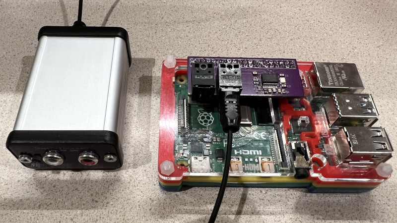
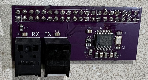
If you’re looking to connect a Raspberry Pi to the optical port of your AV system, [Nick Sayer] has you covered. His “TOSLINK Transceiver Hat” utilizes a WM8804 chip from Cirrus Logic to go from the Pi’s I2S audio output to S/PDIF. From there the signal goes directly into the TOSLINK input and output modules, which have the appropriate fiber optic hardware and drivers built-in. All you have to do from a software standpoint is enable a boot overlay intended for a digital-to-analog converter (DAC) from HiFiBerry.
Speaking of which, comparing this project with commercial offerings from companies like HiFiBerry is somewhat unavoidable. While we can’t say for sure how the simple design [Nick] has come up with compares to more expensive (or even cheaper) options on the commercial market, obviously going the DIY route always nets you extra points here at Hackaday. Plus, we’ve always been fascinated with projects that tackle this relativity rare example of consumer-grade fiber optic technology.
[Nick] is offering his assembled TOSLINK hat for $40 USD on Tindie, but he’s also made all the necessary files available for anyone who wants to build one themselves.


For hams, who like to keep extraneous RF down, and for locations where lightning is a problem, having an optical link that is something like USB is actually very attractive.
In principle you can use those optical TOSLINK modules for any serial data stream up to the bandwidth rating of the modules. I think I have heard of people using them for serial and MIDI and the like.
There is at least one company that makes fiber optic Thunderbolt cables, iirc.
If I recall correctly Thunderbolt (Light Peak at the time) was first developed to use optical fibers as a medium. Still using copper for the power.
I wounder if those optical Thunderbolt cables transfer any power?
Yes, that’s right. Light Peak was the real deal. Unfortunately, it was dumped town to Thunderbolt. Still have some articles of Light Peak on an old HDD.. Light Peak was meant to provide an optical connection between the chips on a motherboard inside a PC, as well. Not just as an external cable connection. Ah, well. I’m still sad and depressed that LP never made it. 😢
PS: I assume it would have been possible to add two copper wires to the optical fibre, to transport power. A coaxial cable’s shielding braid could have been used for one part of the copper connection (minus?) , maybe. The other one could have resided inside at the center, close to the optical fibre. Anyway, these are just my two cents.
That sounds like the Oculus Link cable, their official cable for connecting an Oculus Quest to a PC.
It’s a powered fiberoptic cable, which allows it to be much thinner than an equivalent 5m wire-only USB 3.0 cable — but more expensive.
A TOSLINK ADC also makes a great optically-isolated quadrature digitizer for a VLF SDR. 48 kHz, 16 bits, and (if battery powered) it completely decouples the VLF antenna from any ground loops. Cheap too.
For direct conversion (no mixer) up to 21 kHz, one channel can be E-field, and one H-field, or two orthogonal antennas.
“While we can’t say for sure how the simple design [Nick] has come up with compares to more expensive (or even cheaper) options on the commercial market”
Being purely digital, surely if data goes in one end and comes out the other it scores 10/10, it’s not like the commercial ones generate nicer, warmer digits.
but there is the problem. making sure the data comes in and out without noise because of less then ideal pcb design.
I’ve not had any such problems to date.
How is HDMI related to a fine hi-fi stereo? 🤔
I mean, audiophiles don’t need things like 60″ flat screen TVs or a black/silver colored surround system made from cheap plastic that can be found at the local electronics market.
What they are rather looking for are true semi-professional stereo systems, high quality speakers made from real wood, with low/mid/high frequency speakers each (ribbon tweeters for the highs; pros use plasma tweeters, even), a serious, quality CD/SA-CD or DVD-Audio player in full metal chassis, a record player with moving coil system or laser and a quality tuner/amplifier in a shielded metal chassis with a high quality analog circuit, with big dynamic range and a low noise DAC (say 114db snr and beyond).
Headphone users, by contrast, do use electrostatic headphones from Stax and other companies.
These are wonderful for listening to classic music, for example.
https://en.wikipedia.org/wiki/Signal-to-noise_ratio
https://en.wikipedia.org/wiki/Tweeter
https://en.wikipedia.org/wiki/Plasma_speaker
https://en.wikipedia.org/wiki/Stax_Ltd
HDMI seems to have become the default digital audio cable, probably because its got more bandwidth than TOSLINK (or at least the in service specs for it) so can do lossless surround sound rather than the compressed DTS type stuff. Some musical folks are even going in for surround mixing in the way older music has played with stereo effects, don’t want a lossy compressed surround sound signal there – in a movie you won’t notice as the DTS and Dolbly Digitial pro logic methods that are basically the standard, even the older specs ones are quite good, but when its all about the music you might…
Doesn’t matter what your speakers etc are if you are getting lower grade input to them, and those great CD players etc might output ‘better’ (though being a CD the source can only be as good or worse than other digital media) but the phono cables they tend to use are more likely to pick up interference than the TOSLINK or even HDMI (as those cables pretty much have to be well shielded to work at all)..
Won’t get me changing my system any time soon though, might be old, certainly isn’t the highest end, but it sounds really good, I can happily live with compressed surround with the toslink input keeping the interference issues running though the rats nest at zero and more than capable of ‘lossless’ digital audio..
Many people have their Hi-Fi as part of a larger system, which can include high quality surround sound DACs and separate amplifiers. Even for pure Hi-Fi there are surround sound recordings, it’s not just for the home-cinema. Like it or not HDMI has the highest bandwidth of the digital audio interfaces for uncompressed multi-channel audio, and makes for a convenient standard interface between everything, even for pure-audio uses.
There’s USB sound pods that have TOSlink output *and* input. The one I bought has some issue that results in audible ticks in the sound; i assume its in the driver code somewhere.
Got a link to something that has TOSlink in and can do raw bitstream data?
From where I am standing it could be anything. You maybe right on a driver issue.
But one known issue with the interface is over ‘clock recovery’ from the received signal. This one aspect alone might be the hallmark of a quality receiver.
If this isn’t working the receiver will loose sync and see errors causing lost data due to discarded frames.
Because the AES3 protocol has parity and CRC error detection but has no error correction mechanism that data is lost.
The interface is designed for live audio, such errors might manifest themselves as disruptions to the audio feed.
Transmission systems (especially optical) have to work on recovery clock because even if they are manufactured perfectly to spec each end maybe subject to temperature differences causing timing crystals and other such mechanisms to never be perfect most of the time.
At under 5mbps in 2021 it might seem laughable but this technology is quite old now, when it received its last major spec update the MP3 player wasn’t mainstream.
When it was created there was video tape and audii cassette tape and the Compact Disc was just launching mainstream.
..
Consider buying this device to verify if the problem is from the audio source or the sound pod receiver.
I have several TOSLINK components, but haven’t gotten around to hooking them together.
Has anyone tried replacing to rx/tx modules and fibers with those used for Ethernet to extend the range? Or making a media converter?
I think there are much better ways to transport digital audio over extended ranges nowadays. Heck, if nothing else you could probably go longer with S/PDIF over copper, which is the exact same bitstream as TOSLINK.
I fully admit that my recent obsession with TOSLINK is at least 10 years (heck, probably more like 20+) out of date.
Extended distances may mean complicated power supply circuits and with fiber optics we can avoid ground loops which inevitably creep in with S/PDIF over copper.
But the range of toslink optical is not very far. 10s of metres, while coaxial is upto 150m and other copper specialist equipment maybe longer.
There is little benefit over copper than potential EM interference protection due to copper cable length that causes data loss of a live stream that has no error correction and recovery for lost data.
It is arguable that any environment exists that is within the maximum distance of optical that if you used copper instead that would see EM interference.
The bandwidth available is within the realm of USB v1 at under 5mbit/s with optics lasers specified upto ~10mbit.
The moment you decide to change the optics (to gain you perceived advantage of distance you get from being optical) you might as well revisit if using this tech solution is worth it at all.
There are no extended distances you talk of for the use cases for the design of AES3. Which is basically for studio to live concert hall environment in terms of design transmission range.
You are better off using the Internet with error correction and recovery in that extended distance use case for digital audio transmission. Like the person said above.
..
Thank you to the person that made this project as I have recently purchased optical TX and RX and WM8804 and CS8416 chips as an educational project to build into Arty A7/Z7 FPGA project. This Pi project will help provide pointers on the circuit design and electrical elements. I shall look at purchase to help test against.
I hope to recreate the function of the AES3 protocol decoder and encoder bolted to the side of a uCPU. This means without use of chips WM8804 etc…
Now can I do received clock recovery entirely within the FPGA logic ? Hope to get back to that over the coming months.
If you do S/PDIF over copper right, you’re supposed to use isolation transformers, which moots ground loop concerns.
Now, I can’t remember the last time I saw it actually implemented correctly, but still.
I didn’t think the RPi could output anything other than stereo.
Yes you only get stereo out of the stereo headphone socket.
But if you think in terms of HDMI, bluetooth and ethernet the world is your oyster for audio format choices into and outof a PI.
Digital audio over optical toslink has only a few common supported standards PCM, Dolby Digital, DTS.
But I do not think Dolby Atmos the current 7+1 standard is supported.
This is also a problem for HDMI-ARC (due to ARC bandwidth limitations) but if you have HDMI-eARC you probably also support Dolby Atmos.
Thank you, I didn’t know RPi could play movies in surround sound!
Try a RPi HAT for adding fiber optic audio for your car
https://photos.app.goo.gl/QVJnax1tah1NoJcLA
That’s going to need a long fiber to attach it to the home stereo!
B^)
Hi,
you shoud take a look at this project:
https://github.com/mill1000/raspdif
It maybe just output but doesn’t need any chips.
The one thing you get from using a WM8804 is that it winds up supplying the i2s clock, and can do so with much less jitter. The issue is that if the RPi is the clock source, it can only generate clocks synchronously with its own system clock, and it doesn’t divide down evenly to anything used by digital audio I/O.
Now, is the jitter a fatal flaw in 2021? _Probably_ not, but it’s why the WM8804 is a useful add-on.
It would be nice if someone with the right equipment could measure the jitter to compare the two solutions.
Thanks for the link to the project.
It looks to be an Digital Audio over Phono/Coaxial as “output only” for RPi using bit banging the GPIO pins.
Yes digital audio output is less complex, even if the clock frequency is a little away from specification the receiver does all the hard work to identify, lock onto and decode and maintain synchronisation.
My theory on building a decoder entirely with digital logic is to super-sample the data stream. Mainly for the purpose of an FPGA education project. Maybe the RPi can do this too and implement below algorithm in software ? I can easily try and hook up a optical RX to GPIO pins. A quick google indicates RPI can work upto 125MHz. So it would make sense for me to implement in software the below idea to first try it out to theory, crush numbers, capture streams and refine method, then attempt to offload it to an FPGA design.
So imagine the logic is able to sample 16 times in the period of 1 transmitted bit (because modern technology can easily sample at 50mbit / 50mhz in 2021, note the optics only need to work at expected line transmission speed).
Over time statistically it knows which high-speed tick is the edge of a state change, lets call it tick-0.
It expects the next state change around the end of tick-15 maybe plus or minus 1 tick.
It can now sample the state of 1 bit conveyed in protocol as an average of 5 ticks in the middle, tick-6 through and including tick-10, as the number is odd there is always a winner and no 50/50 headache.
When the transmitted bit state change edge is statistically observed to have moved away from tick-15, tick-0, tick-1 due to clock discrepancies then the receiver will insert or remove 1 high speed tick to bring it back towards tick-0 again.
When I use the term statistically this means that when it is observed to be slightly out of bounds (1 high speed tick out) it increments a counter, but when it is found to be where it is expected, it decrements a counter if the counter is above zero. Only when some threshold is reached does the clock adjustment occur. It acts like a Schmitt Trigger for the error. This is to stop the tick insertion or tick removal operation from flapping.
This is the kind of thing I am expecting my 100MHz capable Arty A7 FPGA might be able to achieve in my project entirely inside logic gates.
Have ordered Nick’s board now although shipping to GB is expensive right now, I’m sure it is worth it :)
I’m really looking forward to getting this working. I’d like to use a RPi Zero W to be a Roon endpoint with Toslink output to a DAC. I already have a full size RPi with a full DAC hat but I’d like to repurpose the RPi and shrink the overall footprint of the Roon endpoint down.
can be detected if Android TV was installed in Raspberry Pi ?