[rctestflight] recently purchased a big CNC router, and that meant it was time to arrange for some dust extraction in the workshop. Naturally, he set about building this himself!
 Using a shop vac is fine at smaller scales, but they can quickly be filled up on bigger jobs. To stop it getting filled up as quickly and wasting vacuum bags, [rctestflight] wanted to build a 3D-printed cyclonic separator to catch and dump the heavier-than-air particles from the routing process into an attached bucket.
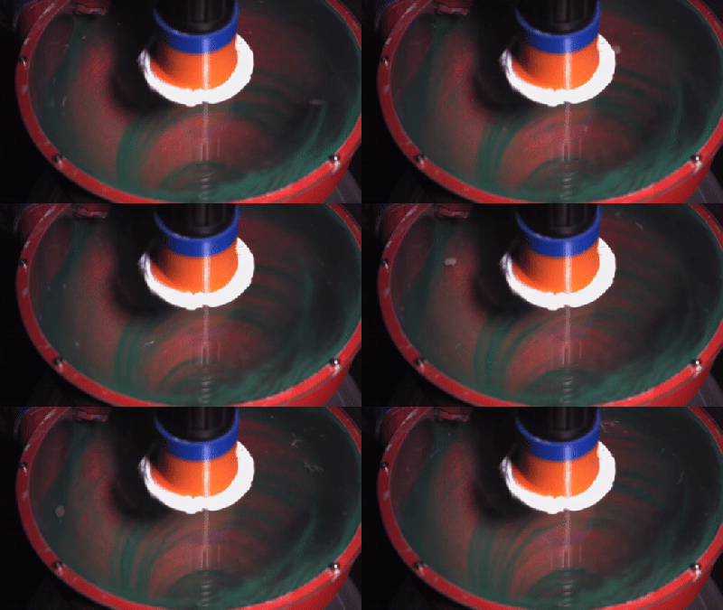
[rctestflight] trialed a variety of designs, from a quad cyclone, to a large single cyclone and even a triple-series design. A diffuser design was also built, that aims to slow the air flow to the point where particles drop out of the air stream. At the end of the day, the large mono-cyclone design proved to be the most effective at removing particles from the airstream.
Fundamentally, if you’re making lots of dust, a cyclonic separator is a great way to go about dealing with the problem. We’ve seen similar builds scaled up to deal with the needs of a whole workshop, too. Video after the break.


There’s “a rat” in separate.
Aussie Rules spelling
I want to make one that separates coarse from fine grit to use with a glass bead cabinet, and a sand blasting cabinet. Get the super fine worn down grit, dust, and removed paint, rust etc out so the remaining large sand and glass can work better.
What would be a nice next step would be a grit washer to clean the remaining fines out. I’ve done that with a small batch of used glass bead. Put some in a can, fill it up with water then agitate to get the fines to the top. Pour off the water and let dry. Then the fines can be carefully poured off, leaving behind the large, cleaned grit. Takes much too long to do that in a container like a tin can. Would need some continuous process.
Well, multiple stages works fine, the worst part is the trial-and-error involved in an optimizing the cone angle & length for the abrasive collection stage. Then you just fancy up the abrasive bucket. To clean up what drops a stir plate under the bucket and a 50mm stir bar in the bucket, some mesh or tray to catch the abrasive (and keep the stir bar free), and something like a fish tank filter near the stirrer (so you don’t deal with pulling abrasive) and can let it keep the water clear (probably needs an appropriate filter mod though).
By that point you might as well add in a heated screw conveyor to dry and move out the material for full loop action. Blast away till your compressor drops! ^_^
Kind of like the one they recently had in an article?
https://hackaday.com/2021/11/30/two-stage-dust-collector-recycles-blasting-media/
Seems like a good use.
Plastic won’t be a good material for such project, given how abrasive the media is.
For dust separation from heavier particulate, you simply need a two stage system, with the first stage having a “tuning port” just below the cyclone. Basically, it’s an adjustable, regulated air leak that allows air to flow up from the bottom of the cone (normally a bad thing). It needs sufficient flow to allow the fine dust to be lifted up and carried through the first stage and on to the second, which is constructed traditionally with a sealed collection chamber.
It was a long time ago, but I remember that there is a relationship between the intake and exit holes. You might also try making the hole on the bottom equal to the intake, to a little bigger. I also agree that the cone looked a bit steep. I dug around and found some background design information. I have not read through it all and cannot attest to the accuracy, but I think this might be a good place to start: Cyclone Building Instructions
BTW, thank you for the post — while I do not have one I have been looking on and off to getting one for the home shop.
The Intake and exit need to be the same area. You also need a short pipe on the exit entering the cone to work as a vortex finder. As you make the inlet / exhaust smaller the cyclone efficiency will improve but the flow rate will drop. As with everything it’s a balance. Make some glue in tuning blocks. The hole at the bottom of the cone is also a balance. As it gets smaller it will get more efficient until the vortex attaches midway down the cone and you will see a ring of dust and the cone tip blocking. Either increase the flow rate or make the tip bigger. Let me know if you want me to design you a cyclone or review any designs.
I hope they do more testing with the size and cone angle. I bet the 3 stage one would work better if they were each a different size or angle to target different size dust.
Once I get a larger volume printer, I may have to experiment as well.
What is there to be said about a system that could also have been made with a set of buckets and a traffic cone…
The video already tells the tale the tinkerer tended to tell, I think.
Yes, a traffic cone, exactly. That´s how I made mine. I only printed the fittings. Works wonder.
But yes this one is better since it can “seperate”. I knew Ozglish was “degenerete”, this title is just confirmation.
http://billpentz.com/woodworking/cyclone/ has done extensive research on cyclones, especially for fine wood dust.
If you look around, you will find there are formulas for this. Its all about the weight and drag on the particles – the speed it comes in, the diameter of the cone, and the momentum of the particles. You can “tune it”. Thats why the series was better for general purpose vacuuming.
I’d be tempted to go and pick up one of the scores of broken Dyson vacuums from the local tip – they seem to have a high attrition rate for such an expensive item.
For those of us who never believed our high school math teacher that said we would need math later in life, can anyone take a stab at the relationship of particle weight vs. speed in the cone to optimize the drop out?
From the YT comment section: https://www.sciencedirect.com/science/article/pii/S0307904X06000291
Let just say its not high school math : https://en.m.wikipedia.org/wiki/Cyclonic_separation
Hi guys. What do you think about SL_ST CYCLONE?
Is it possible to download a model somewhere?