
There is many a comment on these here pages along the lines of “Why did you use a microcontroller, when you could just have easily used a 555 timer!” And, yes, we sometimes agree with the sentiment, but when a chance comment seen by Hackaday.io user [Tim Böscke] suggested turning it around and building a microcontroller out of 555 timers, the gauntlet was well and truly thrown down. Now let’s be clear, this is not the first time we’ve come across this idea, there was a breadboard 555 based build ten years ago, but this is the first time we’ve seen it done by leveraging open source synthesis targeting a PCB!
The first logic element was a simple inverter, constructed by tying the TRIGger and THReShold pins together.
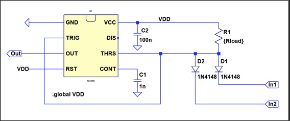
From there it was a simple matter of adding a few diode-resistor networks to the input, to effect a NAND2 gate and a NOR2 gate. Development was speeded up a bit by modeling the logic circuits in LTSpice, to find the best combination of part values. From these simple elements, all further logic functions could be implemented. Next a memory element was needed. As luck would have it, the 555 has a RS flip flop as part of its circuit, fed by dual comparator inputs. All that was needed was to bias the THRS input at Vdd/2 and then feed the data in via a pass transistor, and hey presto! a serviceable, albeit slow latch.
[Tim] has previously created a minimalist CPU called MCPU, with a mere four instructions, designed to fit in a 32 macrocell FPGA, so was able to reuse that design for this project. The fun part was to leverage the PCBFlow toolchain [Tim] maintains, which implements a Yosys synthesis flow with a custom place and route (PnR) backend. A liberty file was produced describing the circuits (macrocells) [Tim] wanted to make use of, then a synthesis script implemented the flow using Yosys/GHDL to elabourate the design, map it into the technology defined earlier, and write out a netlist the PnR tool could use. Helpfully Yosys also writes out a PDF of the design as well as a spice netlist. What a tool!
The PnR tool [Tim] created for PCBFlow was written in python, and outputs the XML format that Eagle can use. Its job is to place the macrocells (deliberately made square) by looking up the appropriate physical circuit, including all passives, dropping them into the PCB, adding the interconnects, and then optimising the layout using simulated annealing, optimising for minimal trace length. We think the result is pretty slick looking, and the approach is something that can easily be reused for other projects in the future.
Thanks [YGDES] for sending this in!


Can you emulate a 555 with it?
I think the universe would collapse on itself if you did.
Also, you could go blind.
:D
I think there must now be more articles referencing the 555 comments than there are actual 555 comments
Arduino.
“elabourate” ?….
Ye olde Queenes Englishe is spelled moure elabourately, because ye olde Queene believes moure vouwels maeke it moure coloureful, a little moure flavour, if you will.
Would you kindly drop by and help me clean my nightly beverage off of my keyboard, screen and desk?
Jolly good send-up goode sir, jolly good.
Yeah, I’m british, so get used to the annoying misspellings. Anyways, you probably want to look up elaboration, if this is a new thing to you.
I built the original referenced breadboard 555 logic (it’s a tiny SRAM). This is an amazing successor, and more along the lines of what I had envisioned. Nice!
BTW what did your project become ? It’s been 10 years now… I didn’t see updates. Tell us more !
It is now at the National Super Computer Laboratory running simulations of massive black holes interacting with anti-dark matter.
(He didn’t stop when he had it running 8 bits at 500 kHz, and decided to implement a few enhancements)
B^)
Nice, I did not know of that before.
I like your idea of the AND-N gate. I implemented it in the toolchain. Unfortunately I have massive problems simulating this “gate-type” due to operating point issues in Spice.
So, want to give your project another go now? ;)
Not to disparage “LTSpice model of a NAND gate implemented with 555 and diodes”, but “that” NAND only needed the diodes, a transistor, and 2 or 3 resistors aka RTL logic. Or just use the diodes and resistor for M2L (mickey mouse logic). It was in a Don Lancaster book that I was introduced to that term (see https://www.tinaja.com/ebooks/cmoscb.pdf).
Where’s the fun in that? Make it as overly complex and pointless as possible. Add some pneumatic logic gates and blinkenlights for fun.
Or you could use a MCU’s or some other complex chip’s Crystal oscillator pins as an inverter. :P
Don’t forget to add a whole chip and use its ESD protection diodes for that NAND gate.
yeah that’s my take too…they make the headline with 555s but really they’re just using it as a buffer or inverter. it looks like the logic is all diodes.
i mean, i’ve definitely used a 555 just to take an analog signal and turn it into binary without worrying about any of the details. but even then, i usually take a little more advantage of its features than this.
I was really hoping for something more like [M. Eric Carr’s] use of a A AND NOT B gate, instead of diode logic followed by an inverter.
stay tuned…..
Where is Nancy Reagan when we need her? Just Say No!
Have you not heard?
Why use a 555 timer when you could have just used a microcontroller?
Now to complete the high level mockery, make it blink a LED.
I understood 555 timer, but the rest was gibberish to me 😂