PCB Art has surely captivated us over the past few years and we’re ever intrigued with the intricate detail the community puts into their work. We’re no strangers to [Arnov]’s work and he has impressed, yet again, with his Kamehameha PCB badge.
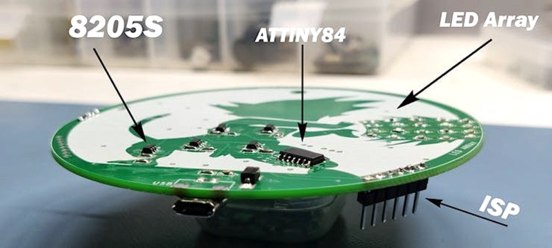
Unfortunately, no 555 timer was used in the making of this project, but don’t let that turn you away. Instead, we have an ATtiny84 microcontroller for implementing the logic to control the LEDs, a MOSFET-based driver for driving current through the LEDs, and, of course, the LEDs to give the “turtle destruction wave” its devastating glow. Pay really close attention to the detail [Arnov] put into the silkscreen as you can see that’s a pretty crucial part of this build.
Aside from marveling at [Arnov]’s work, fans of the OrCAD PCB designing software will learn how to import an image file into their project as [Arnov] walks through that step in his tutorial. He even has some pretty good reflow soldering tips if you’re looking to try your hand at SMD soldering.
Another cool build [Arnov]. Keep it up!


Yeah, talking sh*t about stuff YOU don’t like is the way to go. Here’s your internet points.
Why the 8205s FETs though? Why any external transistors at all?
I don’t its just that a blinky PCB just doens’t really feel like a “badge” in spirit. If it had comms or did something interesting, sure but just a blinky. Yeah I wouldn’t call it a “badge”
That’s a fair point on the “badge” terminology. He included a hole at the top of the board presumably for a lanyard so he can wear it around his neck. So if you think of a “badge” as just some decorative (or functional) ornament that can be worn on your person it seems reasonable in that case. But maybe not so much in the sense that we’ve seen other PCB badges? Just a thought.
so, if its not a badge… what is it going to be called?
How about we call the badges with Comms C-Badges?
https://youtu.be/VqomZQMZQCQ
Every project is a learning opportunity – as long as it is motivating enough to get it done. Whether it is worth featuring on Hackaday is another matter.
Nice job, but I think is a little overkill using a >1USD uC to do this. Some similar effect could be achived for some cents with discrele logic like a 4017 and our beloved 555 :)