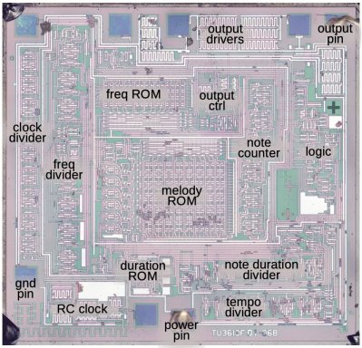
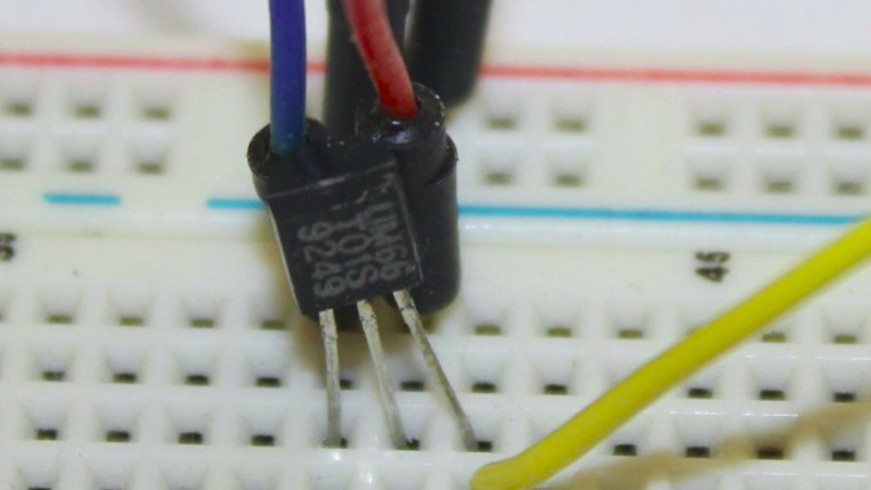
As we approach the moment in the year at which websites enter a festive silly season of scrambling to find any story with a festive angle, we’re pleased to see the ever-reliable [Ken Shirriff] has brought his own take on Christmas tech to the table with a decapping of the UM66T melody chip that has graced so many musical greeting cards.
 The surprise in this age of ubiquitous microcontrollers is that this is not a smart device; instead it’s a single-purpose logic chip whose purpose is to step through a small ROM containing note values and durations, driving a frequency generator to produce the notes themselves. The frequency generator isn’t the divider chain from the RC oscillator that we might expect, instead it’s a shift register arrangement which saves on the transistor count.
Although the UM66 is a three-pin device, there are a few other pins on the die. These are likely to be for testing. As a 30+ year old product its design may be outdated in 2021, but it’s one of those chips that has survived without being superseded because it does its task without the need for improvement. So when you open a card and hear the tinny tones of a piezo speaker this holiday season, spare a thought for the ingenuity of the design behind the chip that makes it all possible.


The most commonly available version is the UM66T19L (Fur Elise). This version of the chip is also found in fake candles. Yes, the random flame-like change of light intensity of fake candles is actually the Fur Elise song playing on an LED. If you connect a speaker to it you can hear it!
Fuer Elise if you can’t type the ü.
or Feuer Elise in case of the candle
EMS’ Windell Oskay did a great piece on this years ago – shows how the chip and LED fit together and how to amp it up with a big LED
https://www.evilmadscientist.com/2011/does-this-led-sound-funny-to-you/
How could this possibly work without either a 555 timer, a microcontroller or both?!
Let’s see, it has a clock, various ROMs, various dividers (i.e. ALU), and a counter. It may not be a microcontroller, but it is a microprocessor.
B^)
Too weak. Needs an Intel i9 on an E-ATX motherboard with 32 GB RAM instslled, at minimum.
Could used an Arduino for that.
Available tunes list:
https://1.bp.blogspot.com/-og3IwY4jiGw/XmXqSLbZcaI/AAAAAAAAArA/IzkpKDPizCcVevqKCVl3GGgckd1HNbfqQCK4BGAYYCw/s1600/table2.jpg
It could use some more cowbell.
Hell of a FSM. I can imagine the ROM being EEPROM and being updated as needed for each song.
They give up flexibility when they went to three pins. Thirty years ago Radio Shack sold a melody IC, 14 or 16 pin DIP. You could sequence through a number of melodies, though no way to set it to one.
But I assume these are cheaper, and beggars can’t be choosers.
I bought one of those when they came out.
I had great plans for it.
(crickets)
I’ve got an old video game that uses the same technique to generate a colored startfieid background, eliminating that processing load from the old Z80. There’s a mux that cuts in the Z80 generated video when needed. Roms with counters were the low cost micros of the day.
Random hack: the flashing SMD LEDs can be hacked apparently, by using a blue laser to “zap” adjacent pads. Supposedly they can be turned into flickering LEDs.
I accidentally connected the earlier version of this chip (epoxy capped die soldered on board) in reverse polarity and now some notes are completely wrong. How do I fix this?