No Acid: Open ICs With A Tesla Coil

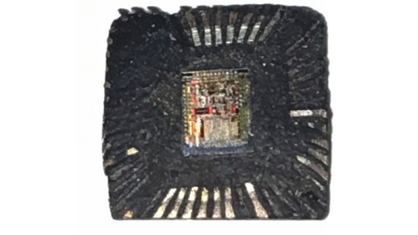
We’ve taken ICs apart before, but if they are in an epoxy package, it requires some lab gear and a lot of safety. Typically, you’ll heat the part and use fuming nitric acid (nasty stuff) in a cavity milled into the part to remove the epoxy over the die. While [100dollarhacker] doesn’t provide much detail, he appears to have used a Tesla coil to do it — no hot acid required.

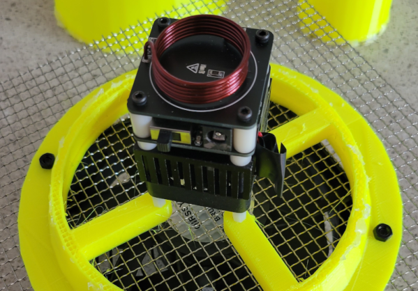
Initial results were promising but took a long time to work. In addition, the coil gets very hot, and there is a chance of flames. The next attempt used a 3D printed cone with a fan to push the plasma over the chip. The first attempt shorted something out, and so far, each attempt eventually burns out the MOSFET driver.

We are always interested in the practical uses of Tesla coils and what’s inside ICs, so this project naturally appealed to us. We hope to see more success reported on the Hackaday.io page soon. Meanwhile, if you have a coil and an old IC lying around, try it. Maybe you’ll figure out how to make it work well and if you do, let us know.

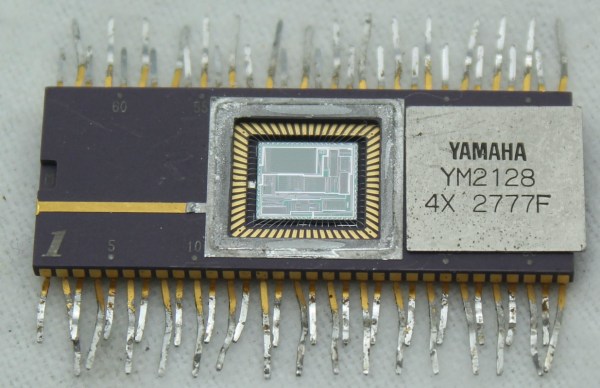
The easiest chips to open are ceramic packages with a gold lid. Just use a hobby knife. There are less noxious chemicals you can use. If you want to use fuming nitric, be sure you know what you are doing and maybe make some yourself.

A Particularly Festive Chip Decapping

As we approach the moment in the year at which websites enter a festive silly season of scrambling to find any story with a festive angle, we’re pleased to see the ever-reliable [Ken Shirriff] has brought his own take on Christmas tech to the table with a decapping of the UM66T melody chip that has graced so many musical greeting cards.

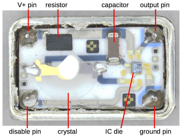
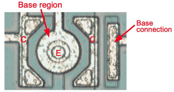
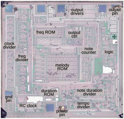
The surprise in this age of ubiquitous microcontrollers is that this is not a smart device; instead it’s a single-purpose logic chip whose purpose is to step through a small ROM containing note values and durations, driving a frequency generator to produce the notes themselves. The frequency generator isn’t the divider chain from the RC oscillator that we might expect, instead it’s a shift register arrangement which saves on the transistor count.

Although the UM66 is a three-pin device, there are a few other pins on the die. These are likely to be for testing. As a 30+ year old product its design may be outdated in 2021, but it’s one of those chips that has survived without being superseded because it does its task without the need for improvement. So when you open a card and hear the tinny tones of a piezo speaker this holiday season, spare a thought for the ingenuity of the design behind the chip that makes it all possible.

Ken Shirriff Breaks Open The Yamaha DX7

For better or worse, this synthesizer was king in the 1980s music scene. Sure, there had been synthesizers before, but none acheived the sudden popularity of Yamaha’s DX7. “Take on Me?” “Highway to the Dangerzone”?  That harmonica solo in “What’s Love Got to Do With It?”  All DX7. This synth was everywhere in pop music at the time, and now we can all get some insight from taking a look at this de-capped chip from [Ken Shirriff].

To be clear, by “look” that’s exactly what we mean in this case, as [Ken] is reverse-engineering the YM21280 — the waveform generator of the DX7 — from photos. He took around 100 photos of the de-capped chip with a microscope, composited them, and then analyzed them painstakingly. The detail in his report is remarkable as he is able to show individual logic gates thanks to his powerful microscope. From there he can show exactly how the chip works down to each individual adder and array of memory.

[Ken]’s hope is that this work improves the understanding of the Yamaha DX7 chips enough to build more accurate emulators. Yamaha stopped producing the synthesizer in 1989 but its ubiquity makes it a popular, if niche, platform for music even today. Of course you don’t need a synthesizer to make excellent music. The next pop culture trend, grunge, essentially was a rebellion to the 80s explosion of synths and neon colors and we’ve seen some unique ways of exploring this era of music as well.

Thanks to [Folkert] for the tip!

[Ken Shirriff] Picks Apart Mystery Chip From Twitter Photo

It’s no secret that the work of [Ken Shirriff] graces the front pages of Hackaday quite frequently. He’s back again, this time reverse engineering a comparator chip from a photo on Twitter. The mysterious chip was decapped, photographed under a microscope, and subsequently posted on the internet with an open call to figure out what it did.

[Ken] stepped up, and at first glance, it was obvious that most of the chip is unused, and there appeared to be four copies of the same circuit. After identifying resistors and the different transistor types, [Ken] found differential pairs.

Differential pairs form the heart of most op-amps, and by chaining them together, you can get a strong enough signal to treat it as a logic signal. Based on the design and materials, [Ken] estimates the chip is from the 1970s. Given that it appears to be ECL (Emitter-Coupled Logic), it could just be four comparators. But there are still a few things that don’t add up as two comparators have additional inverted outputs. Searching the part number offered few if any clues, so this will remain somewhat a mystery.

We’ve covered [Ken’s] incredible chip sleuthing before here, such as the Sharp EL-8 from 1969.

Inside An Oscillator With [Ken Shirriff]

We are always glad to see [Ken Shirriff] tear into something new and this month he’s looking inside a quartz oscillator module. Offhand, you’d think there’s not much to these. A slab of quartz and some sort of inverter, right? But as [Ken] mentions, “There’s more happening in the module than I expected…”

If you’ve ever wanted to decap devices, big hybrid modules like these are a good way to get started since you don’t need exotic chemicals to get at the insides. [Ken] managed to break the fragile crystal wafer on the way in. Inside was also a small CMOS IC die. Time to get out the microscope.

If you follow [Ken’s] blog, you know he’s no stranger to analyzing IC dice. The oscillator IC is a pretty standard Colpitts oscillator but it also provides a programmable divider and output drive.

The circuit uses some unusually configured capacitors. [Ken] takes the time to point out CMOS logic structures throughout. If you haven’t seen one of [Ken’s] deep dives before, before, it’s a great introduction.

You can learn more about crystal oscillator theory. We used some test equipment to characterize a crystal a few years ago.

Comparing Bare Silicon On Two Game Boy Audio Chips

We always look forward to a new blog post by [Ken Shirriff] and this latest one didn’t cure us of that. His topic this time? Comparing two Game Boy audio chips. People have noticed before that the Game Boy Color sounds very different than a classic Game Boy, and he wanted to find out why. If you know his work, you won’t be surprised to find out the comparison included stripping the die out of the IC packaging.

[Ken’s] explanation of how transistors, resistors, and capacitors appear on the die are helpfully illustrated with photomicrographs. He points out how resistors are notoriously hard to build accurately on a production IC. Many differences can affect the absolute value, so designs try not to count on exact values or, if they do, resort to things like laser trimming or other tricks.

Capacitors, however, are different. The exact value of a capacitor may be hard to guess beforehand, but the ratio of two or more capacitor values on the same chip will be very precise. This is because the dielectric — the oxide layer of the chip — will be very uniform and the photographic process controls the planar area of the capacitor plates with great precision.

We’ve decapsulated chips before, and we have to say that if you are just starting to look at chips at the die level, these big chips with bipolar transistors are much easier to deal with than the fine and dense geometries you’d find even in something like a CPU from the 1980s.

We always enjoy checking in with [Ken]. Sometime’s he’s taking apart nuclear missiles. Sometimes he is repairing an old computer. But it is always interesting.

Decap ICs Without The Peril

There can be few of us who haven’t gazed with fascination upon the work of IC decappers, whether they are showing us classic devices from the early years of mass semiconductor manufacture, or reverse-engineering the latest and greatest. But so often their work appears to require some hardcore scientific equipment or particularly dangerous chemicals. We’ve never thought we might be able to join the fun. [Generic Human] is out to change all that, by decapping chips using commonly available chemicals and easy to apply techniques. In particular, we discover through their work that rosin — the same rosin whose smell you will be familiar with from soldering flux — can be used to dissolve IC packaging.

Of course, ICs that dissolved easily in the face of soldering wouldn’t meet commercial success, so an experiment with flux meets little success. Pure rosin, however, appears to be an effective decapping agent. [Generic Human] shows us a motherboard voltage regulator boiled in the stuff. When the rosin is removed with acetone, there among the debris is the silicon die, reminding us just how tiny these things are. We’re sure you’ll all be anxious to try it for yourselves, now, so take a while to look at the video below showing their CCC Congress talk.

The master of chip decapping is of course [Ken Shirriff], whose work we’ve featured many times. Our editor [Mike Szczys] interviewed him last year, and it’s well worth a look.

Continue reading “Decap ICs Without The Peril”