The lower the frequency of radio transmission, the more antenna that will be needed in general. [OM0ET] wanted to work the 80M to 20M ham bands and decided to turn to a frame antenna. You can see the project in the video below.
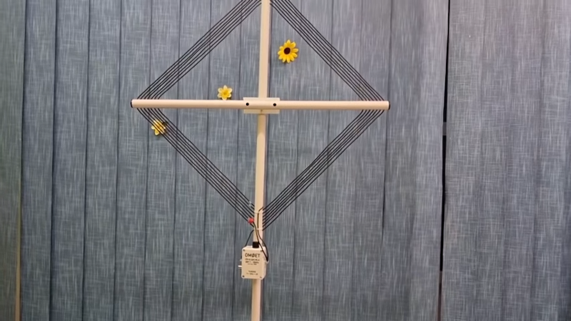
The antenna looks a lot like a magnetic loop antenna. The one in the video has seven loops forming a 520mm square. The loop is, of course, an inductor and by removing some insulation, the operator can clip a lead at different points to control the inductance. A variable capacitor resonates the antenna, so there is definitely tuning required.
The physical support for the antenna is 25mm PVC. It isn’t that hard to build, but does it really work? The video shows quite a bit of detail on the construction, but we are waiting for part two which will show the operating tests. From past experience, we will guess it will work well enough, but the tuning will be sharp, meaning you’ll have to retune a lot when changing frequencies.
Also, these kinds of antennas tend to be directional, so they are useful in fox hunting. We see a lot of loop antennas for hiding in plain sight or, sometimes, for portable use.


I assume this is receive only. If for transmitting there can be hundreds of volts across the tuning cap. Danger if used indoors where contact with tuning cap is possible.
These loops are great for AM-MW listening. A single turn loop smaller and in the middle to plug in to a car radio. Place the whole loop against a portable with it’s built in loop/loop-stick antenna.
I’ve built many of these, and the capacitors for tuning. Mostly for receiving, but I made one for 20m transmitting back in the day. I recommend hitting up the hardware store for aluminum flashing, which can be had for less than $10 for a 1’x10′ roll. More than enough for dozens of capacitors. It’s an excellent capacitor plate material for a low cost. One may have to flatten it a bit, but it works and can be cut with robust scissors.
The actual construction of the capacitor in terms of the number of plates and their surface area isn’t too critical. There are many calculators out there for air-variable capacitors. Build it a little bigger than you think you need it and you can trim it through removing plates or cutting them down, if necessary.
Note: every hardware store web site I have seen has the thickness dimension frequently wrong. It is nowhere near .100″ – that would be more of a ‘plate” than a “sheet”. I believe I measured it through the years as .009-.010″, on average.
Looking at the frequency-domain display on an SDR dramatically shows how the tuning makes a huge difference. I was pulling in stations that I didn’t even know were there on the US AM bands(~500-1700kHz).
Building your plate capacitors, I would like to see an article about that!
Same!
https://www.qsl.net/k4dfh/DL5DBM.HV.AVCap.html
Thank you!
There’s also the wonder and joy of trombone capacitors! http://www.alexloop.com/artigo36.html
Small correction: the plastic tube frame is NOT PVC, it’s CPVC. It’s easy to tell by the color. PVC is white (plumbing use) or grey (electrical use). CPVC is a tanish color. They are not interchangeable. Different fittings and glue. CPVC can also withstand much higher temperatures, thought is still plastic and will burn if exposed to flames. Both CPVC and PVC are wonderfully easy to work with. Normally, I would never comment about such things, but your articles are very technical and deal with subjects in a scientific and accurate manor and all details should be correct. You all are fantastic in the way you deal with technology.
My dad built an award winning (contest was for number of stations received at a fixed location) based on that idea. its also a good antenna for nulling out strong stations if you can find their direction and rotate the antenna. photo of it in the center here) https://photos.app.goo.gl/ktDFDizq2EbwaMdS6
I was considering this myself recently after reverberating the built in frame antennas in the old valve portable radios for MW and LW. It was in the lid. But I decided to knock up an active antenna instead . Pleased to see this, it gives me an idea on a bigger scale . Well done.