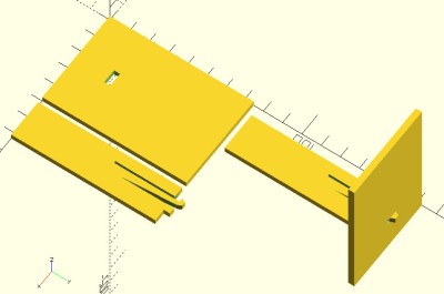
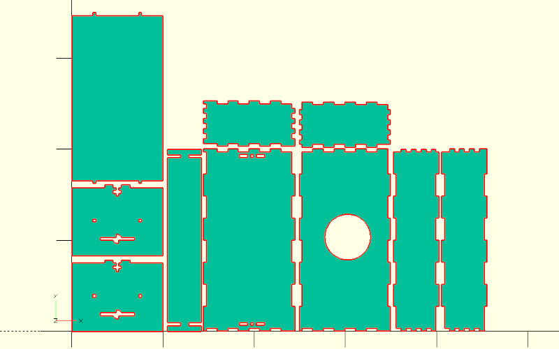
While there’s always the edge case, there’s a strong likelihood that if you’re using OpenSCAD, you’re probably working on a CAD model that you intend to 3D print at some point. Of course that’s not to say this is all you can do in OpenSCAD, but it’s arguably what it does best. If you wanted to make artistic models, or maybe render what your new kitchen will look like, there are other tools better suited to such tasks.
But thanks to lasercut.scad, a library that [Brendan Sleight] has been working on for the last several years, we might have to reconsider our preconceived dimensional notions. Instead of designing parts for 3D printing, his library is all about creating parts intended for subtractive manufacturing. Originally (as the name implies) it was geared towards laser cutting, but the project has since evolved to support CNC routers, vinyl cutters, and pretty much anything else that can follow a DXF file.

The library has functions for creating the standard tricks used to build things from laser-cut pieces, like finger joints, captive nuts, and assembly tabs. If it was something you once saw holding together an old wooden 3D printer kit back in the day, you can probably recreate it with lasercut.scad. It even supports a pretty wild piece of rotational joinery, courtesy of [Martin Raynsford].
Don’t have a way of concentrating a sufficient number of angry photons at your workpiece? No worries. The library has since been adapted to take into account a parametric kerf width, which lets you dial in how much of a bite your particular tool will take from the material when it does the business. There are even special functions for dealing with very thin cuts, which [Brendan] demonstrates by assembling a box from sheet vinyl.
Of course, those who’ve used OpenSCAD will know there’s not an “Export for CNC” button anywhere in the stock interface. So to actually take your design and produce a file your cutter can understand, [Brendan] has included a Bash script that will run the necessary OpenSCAD incantations to produce a 2D DXF file.
[Brendan] decided to send this one in after he saw the aluminum enclosure OpenSCAD library we covered recently. If you’ve got your own pet project that bends some piece of hardware or software to your will, don’t be shy to let us know.


Very cool. Will look into this further for some upcoming work.
I really should start/learn using OpenSCAD someday. So far every time I tried it turned out very quickly that someday was going to be some other day.
I’ve had good luck using BlockSCAD as a front-end:
https://www.blockscad3d.com/editor/#
Love it!!! Great job!
Would be much more useful if it could be used with CNC routers/mills as opposed to just lasers.
OIC, never mind. Missed:
>The library has since been adapted to take into account a parametric kerf width, which lets you dial in how much of a bite your particular tool will take from the material when it does the business.
It can, see https://github.com/bmsleight/lasercut#finger-joints-milled and the parameter milling_bit=3.125.
Laser, CNC or vinyl cutters.
How does it handle a round endmill? I’ve found the gyrations for that rather awkward.
So just to be clear, you didn’t even get through the second paragraph before you scrolled down to leave a complaint in the comments?
Yes. Hazards of a site which doesn’t allow editing
Wow, it’s literally in the summary.
A better way to do edge castellations is to cut a straight edge (without castellations), and then make a 2nd pass of rectangles to cut out the castellations in the straight edge.
This uses only a tiny bit more stock, but it makes it much (much!) easier to adjust the castellation depths and widths for a snug fit.
Trying to adjust castellations that are part of the design of the piece is a nightmare, as any changes to the “teeth” will invariably change the dimensions of that piece.
Much better to overlay the teeth as separate cutouts, and as a library function define the castellation on endpoints to separate the functions. Then it’s easy to adjust depth and width without affecting the endpoints.
>Trying to adjust castellations that are part of the design of the piece is a nightmare, as any changes to the “teeth” will invariably change the dimensions of that piece.
Not well documented (yet), but global kerf can be used.
kerf=0.0;// Hacky global for kerf
The rest (the castellations) are automatically calculated – see num_fingers=4 and/or as an array
Simple finger joints – parameters are direction, startup tap, even number) so for example [UP, 1, 4] – UP direction, starting with a tab not a gap, four figners.
finger_joints=[
[UP, 1, 4],
[DOWN, 1, 4]
]
Whoa!
That is too much power for mere mortals!
B^)
Excellent! I have been using OpenSCAD projection() to produce DXF files for laser cutting too. I found it very useful to be able to model a complete assembly in 3D, and then generate the flat parts from the same file. This library would have made it easier. I’ll give it a try next time. Thanks.