I was rebuilding one of my 3D printers — again — and decided I needed a display upgrade. A color screen is nice, but there are some limitations. I also found there are ways around these limitations, so I wanted to share my thoughts on a dual-mode color touch screen LCD controller for your 3D printer. The screen in question is a TFT35 from BigTree Tech. It is similar to an MKS screen, but it can operate in two different modes, as you will see.
A few years ago, I picked up an Anet A8 which was very inexpensive, especially on sale. Not the best printer, though, because it has that cheap acrylic frame. No problem. A box full of aluminum extrusion later, the printer was reborn. Over time, I’ve completely reworked the extrusion system and the Y-axis, leaving only the motors, bearings, and the controller/display as the original.
That last part was what bothered me. The Anet board is actually pretty capable for a small cheap board. But it is just what the printer needs and nothing more. If you wanted to hack the printer there was very little memory left and only one spare pin for I/O. So it was time to replace the board and why not the controller, too?
The A8 has an LCD2004. That means it has a 20×4 LCD. Instead of an encoder knob, there are five buttons: basically up, down, left, right, and enter. Most printers now have an LCD12864 which, as you can probably guess, is a 128×64 LCD and they use an encoder knob for direction that you can push for the enter key.
Along Came a Spider
I happened to have one of these lying around so when I installed a new motherboard — a Fysetc Spider if you are curious — I also wired in the new LCD. I had to recompile Marlin, of course, but that’s easy. It all worked, it just looked a little bland.
There’s another way to control a printer, and it’s one you may have thought of before. Since the printer accepts commands via a serial port, you could take a computer like a Raspberry Pi with a nice LCD and just have it issue commands to the serial port. Bonus points if the board has more than one serial port so you can still hook up a PC or a Raspberry Pi running Octoprint or similar. Turns out, you don’t have to build this. The MKS touchscreen uses an ARM chip (it isn’t a Pi, though) and has a touch screen that you can use to control the printer. These come in different sizes and are usually called something like TFT35 for 3.5 inch display.
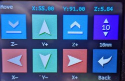
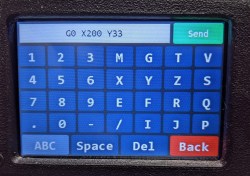
The advantage isn’t just appearance. Having a bunch of touch screen buttons makes many things easier. For example, if the printer is at (0,0) and you want to jog the head to (100,200), that ends up being a lot of button pushes in Marlin. With the touch display, you can bring up a navigation screen that makes it easy. Or, you can bring up an entire terminal and enter G-code. When you press Send, it shows the results of the command, if any. You can set a temperature with the knob, on-screen buttons, or press the number and type in what you want with a virtual keypad.
Split Personality
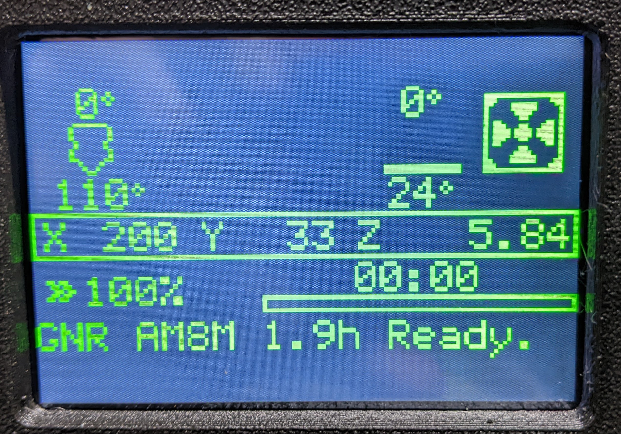
These displays are colorful and nice, but there are a few things they can’t do. Marlin has some wizards and user interaction that insist on a proper, local LCD. But the Marlin code thinks the MKS display is a remote host computer, connected over serial. Displays that can act like both types of LCDs are a sweet hack, and here’s the part that was never clear to me before: these displays can switch modes during printer operation. In other words, it is not a case of selecting a mode and rebooting everything. You can be looking at the colorful touchscreen, then switch over to the stock display while printing and then switch back any time you want. The best of both worlds.
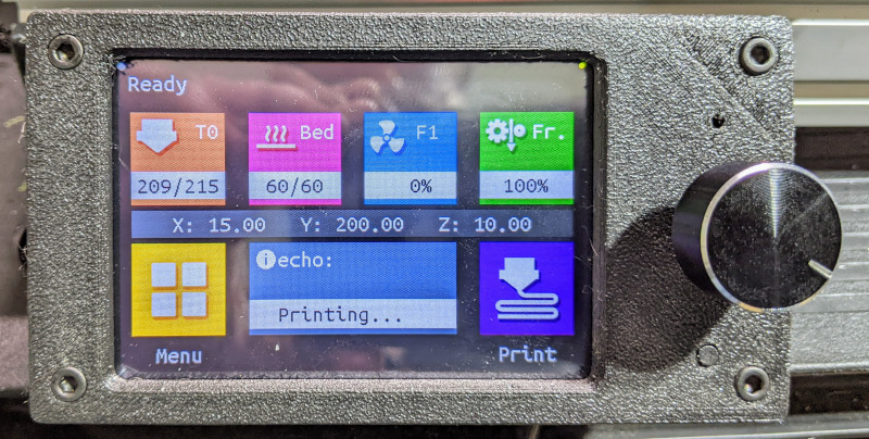
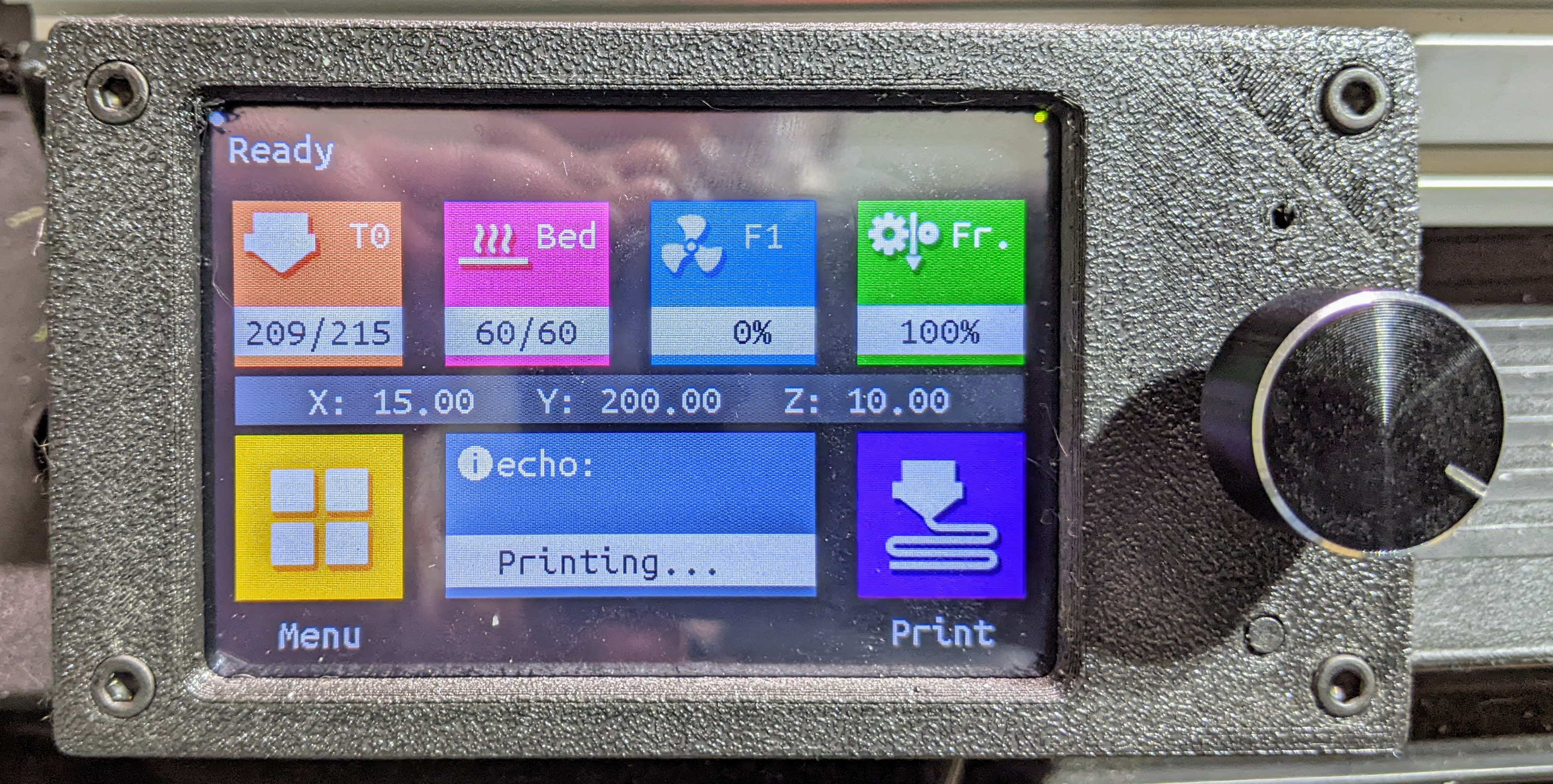
On the face of it, the display looks like an MKS TFT. You have colorful menus and a touch screen. The connection for that is a simple two-wire serial port, along with — of course — power, ground, and an optional reset connection. They provide a cable you can use or modify to connect to your setup. There is also an EXT3 port for boards that have that connector.
If all you want is an MKS display, you are done. Since the display looks like a host computer, you don’t even have to recompile Marlin if the serial port you used was active. In my case, the second serial port wasn’t set up, so I had to recompile, but I do that often enough, anyway.
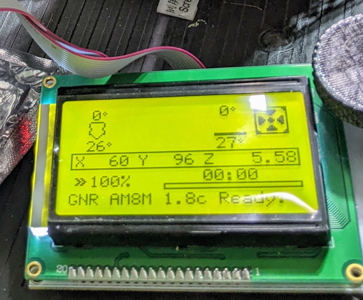
However, if you wire the normal EXT1 and EXT2 ribbon cables to your printer, the display can emulate a normal 128×64 LCD. If you are already set up to use one of these displays, you should not need to recompile Marlin to use this display. However, if you are set up for a different type of display, you’ll need to tell Marlin to use the normal “REPRAP DISCOUNT GRAPHICS CONTROLLER.”
Poor Marketing
Here’s what I never understood about the device. Looking at the write-up about it on different vendor sites like Amazon, Banggood, or AliExpress, it sounded like you could use the screen in either mode as a static configuration choice. In other words, you might wire up EXT1 and EXT2 and then use the emulated mode until you decided to switch over to serial at some future date. But that’s not how it works. You can connect all the cables and switch back and forth between display systems on the fly.
That’s huge. It means you can have a nice user interface that lets you control the printer, print from an SD card or USB stick, and even make customizations to the menu with the source code provided on GitHub or with a simple configuration file edit. (And, yes, you can add custom menu items simply.) But when you need to do something very specific to Marlin, or a new feature shows up that the LCD doesn’t know about yet, you can simply switch to the Marlin display mode. Then you can switch back.
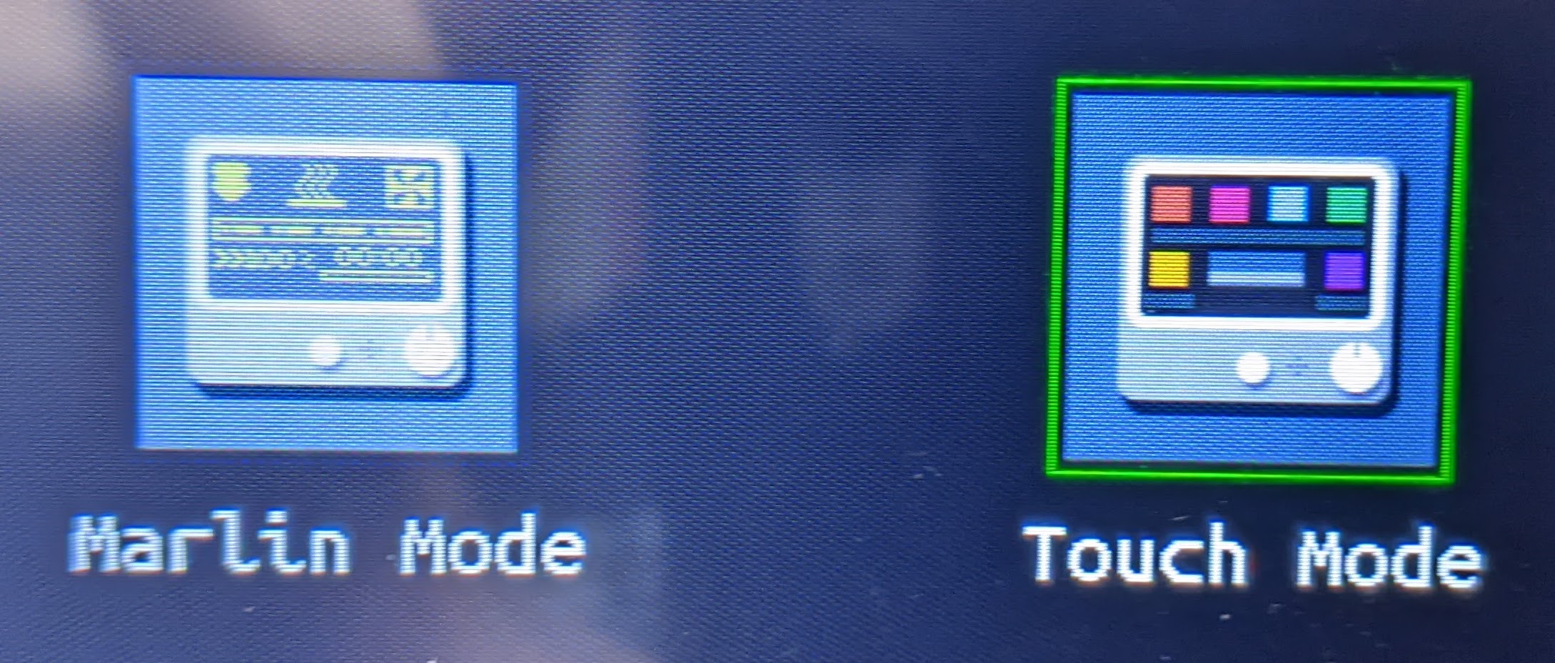
The process to switch is simple. Just hold down the encoder knob or push the screen for a few seconds. A screen will show up allowing you to pick the Marlin mode or the BTT mode. Just touch the one you want. In Marlin mode, the touchscreen does nothing except switch modes, so you might want to use that method. If you hold the encoder down in Marlin mode, the printer will also see the repeated enter keys until the LCD pops up the selection screen.
If you use a bezel, be careful. If you tighten a case down enough to make the touch screen think you are pressing the screen, you’ll get stuck in the selection mode, which makes sense. Just don’t overtighten the LCD!
Installation
Installing the LCD was straightforward save a few problems. For some reason, the pin 1 designation for EXP1 and EXP2 are not consistent among vendors. A Geeetech display worked fine with the Spider board, but the TFT35 didn’t want to come up in Marlin mode at all. I applied power at the serial port and the board appeared hung. The answer was to snip off the alignment tabs on the ribbon cables and flip them 180 degrees.
The serial port was also a mystery. With so little documentation on anything, I just soldered the power and ground wires and then hand twisted RX and TX so I could swap them until it worked. As I expected, the cable needed a cross on those lines to work. You also have to match the display’s baud rate to the port you are using.
After that, it all worked fine. The EXP1 and EXP2 connectors do connect to the board’s reset, so you don’t need to wire the serial port’s reset pin if you have those connected. However, I did notice that switching the mainboard to DFU mode will sometimes fail with the display plugged in. Reflashing the display requires an SD card that flashes a binary file and then reboots and loads fonts and icons. If it is connected to the Spider, it sometimes hangs when trying to reboot during an update. It also works sometimes, though, so I suspect it is just loading on the reset line. In any event, popping the connectors will make it work if you don’t want to try repeatedly.
The display has a number of other ports, but you probably shouldn’t use them. For example, there’s a port for a filament runout sensor. But if you connect it there, it will only work if you are printing using an SD card or USB stick in the display. A better option is to connect it to your printer and tell Marlin to notify the host if a filament break occurs. This will work with the display or something like Octoprint.
In theory, you should be able to connect Octoprint itself through one of the extra serial ports. However, I never got this to fully work. The subordinate port seems to work pretty well, but it never sends Octoprint acknowledgments so Octoprint waits forever or until you force it to continue — use the Fake Acknowledgment button in the terminal. Since the Spider has multiple serial ports, it isn’t a big deal, but in theory, the TFT should work a little better if it can intercept and filter the data stream between the printer and the host software. In practice, I don’t really notice any problems. Some Octoprint plugins like DisplayLayer can send status information to the TFT, anyway.
The Verdict
The truth is, I don’t switch over to Marlin mode very often, but it is nice to have it if I want it, and you can even change the colors to suit you. I really wanted the passthrough mode to work but couldn’t figure out what was going on without digging into the source code, and that might be a project for another day.
Another note: Using the jog keys sets the printer to relative mode. If you are used to popping codes into a terminal, you might want to get used to issuing a G90 before you send a move because the TFT will change it to relative anytime you do a jog.
These displays are inexpensive and easy to interface and since they can still work as a classic display, there’s no reason not to do this easy upgrade. There are plenty of mounting options you can print, of course. The finished result looks great and doing things like moving in both X and Y are much easier with the new display.


Gotta ask – did you pick the A8 up in a FIRE SALE? (Buh-dump-bump *tiss*)
As an A8 owner, I approve of this joke.
I soldered wire directly to the bed heater, and at least that part of the machine has worked flawlessly for four years now. (https://hackaday.com/2017/12/08/how-cheap-can-a-3d-printer-get-the-anet-a8/#the-really-bad-news)
They also have the TFT7.0 which has a Tri-mode which will allow you HDMI input from a Raspberry Pi and Marlin mode _and_ touch screen mode. But you can’t get ahold of them separately because they are a part of their BIQU BX printers that were recently released. If I could snag one of these from _somewhere_ it would be the ultimate 3D printer control screen.
Sorry, the TFT70-BX is distinct from the TFT70. The non-BX labeled one exists and is available elsewhere, but the -BX version is the one with the HDMI adapter on it and mode switching capability.
Hey ThantiK
It seems that (at least in Europe) you can order the TFT70-BX V2.0 for about €90,-
https://www.3dprima.com/spare-parts-accessories/manufacturers/biqu/biqu-bx-touch-screen-btt-tft70-bx-v2-0/a-26109?currency=EUR
While that one has the same part number, I noticed something missing from the product shots — the actual TFT70-BX that BIQU makes, actually has an accompanying daughter board that allows HDMI usage and this one does not seem to have that. I guess I will have to reach out and see if the store maybe just is missing a part.
There are like 5+ different versions of the tft35 from BTT, but a huge plus is that you can compile you own firmware for the displays.
https://github.com/bigtreetech/BIGTREETECH-TouchScreenFirmware/
Bonus is as of Dec 2019 we incorporated a simple porting structure for many other screens like Geetech, MKS, Delta and some new features in the pipe will allow pseudo access to octopi setups, tandem printing (where one printer controls many similar nodes)
I just bought and installed the tft35 e3 v3.it cannot switch modes while printing as you said above.its annoying as if I print from TFT sdcard port I cannot switch to marlin mode and tune print settings and vice versa.from what I’ve read online it is meant to be this way.am I wrong?.is there a way to correct this?. cheers
Odd, it works with mine. Have you tried flashing the latest firmware? Are you trying to switch modes with the encoder (push/hold) or the screen (long press)?
I don’t understand how you failed to recognize the two modes can be used at any time, you are the first I’ve seen to make this mistake. However most people I know are not your average 3D printer owners I suppose.
I have many devices that can work in one of several modes but not at the same time. Use serial OR USB, boot Linux OR Windows, etc.
Originally it was a “recompile and flash” to switch modes, the addition of the dual mode on the fly is only recent , when first introduced it caused a lot of head scratching as users didnt know which mode was correct and the code to switch to which ever link is in use was buggy so it was decided to run both at once with a passthrough to a 3rd uart for ESP/Octopi which has both blocking and non-blocking modes.
I am curious how the octopi pass through works. With my experiments it never sent any acknowledgments back to the raspberry pi and therefore was unusable. It was sort of work but as soon as the pi is waiting for an acknowledgment it waits forever. What’s the trick?
it’s not that recent been using that feature for about like 2.5 years now
I’m late to the party, but switching screen modes is dependent on the media it is using.
Thank you for your informative article. I am at that point now for an upgrade so will up more along your lines.
I’ve done it. I’m in the process of converting my Anet into a Biqu B1 clone