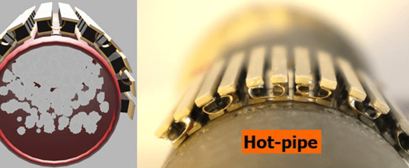
We all know that you can convert heat into electricity. Usually, you do that with some form of steam, but there are other methods, too, including thermocouples. If you’ve ever seen something producing waste heat, you’ll appreciate Penn State’s work to harvest power from hot pipes. The idea is simple in theory: create a flexible thermoelectric generator that can wrap around hot pipes or other surfaces to gather otherwise lost heat. The full (paywalled) paper is also available.
The devices can produce up to 150% more power per unit area compared to other thermoelectric generators. A three-square-inch test device produced over 50 watts. Scale that up to an industrial pipe hundreds of feet long, and you could create some serious power. To accomplish this, the scientists used strips of six thermocouples and connected them for a total of 72 thermocouples. Liquid metal between layers improved the device’s performance.
This isn’t a totally new idea. Russia was famous for making radios in the 1950s that operated using a generator that went around the flue of a kerosene lamp. Since the Russians were pulling this off in the 1950s, converting heat into electricity is obviously nothing new. Of course, your body creates heat, too, so why not use that?


would anyone know if thermocouples as used in this article would be available from uncle jeff or ebay?
Typically thermocouples are tiny things, used to measure temperature.
Just to do a back-of-napkin break-even analysis.
Knowing universities they would probably get their supplies from Sigma Aldric.
I’d start by playing around with iron and copper foil.
You can use Peltier junctions in a pinch. They are optimized for the reverse, peltier effect (using energy to move heat from one side of a plate to the other)… But they do generate energy if used in this way. Very low current is the downside due to material resistance.
Fact is they’re quite often used in those battery free wood stove fans that you’ve probably seen if you’ve even been out in the country in a farm store.
The original term for these was Seebeck generators, after their inventor, Thomas Seebeck. NASA uses these in their RTGs (Radioisotope Thermoelectric Generator).
https://en.m.wikipedia.org/wiki/Thermoelectric_generator
Lost the link in my first post…
I reacted to “50W for 3 square inches”.
I have problems getting 0,5W with Peltier from Conrad. With Peltier from Ebay 0,3W.
I have optimized the construction 5 times and used 8 tealights (heats up to 150 degrees which I understand is max). Passive cooling with heat pipes. Double Peltier elements in series to get more than 2 volts.
Have they managed to get 100 times more? Or am I doing something wrong? The videos from youtube are obviously fake.
They didnt use peltiers here. The article said they used liquid metal to improve the devices performace so its very likely this is a custom formed thermocouple that may not have the same max temp as a peltier. That said to get 50w over 3 square inches is insane. How much heat is being lost by the pipe they’re using? My guess is that its a lot or was custom built for this experiment (and probably a flue from a burner reaching very high and constant temps)
My first guess would be that while they may be getting a somewhat better efficiency percentage than your standard Peltier devices are capable of they are probably, also, getting that result from a much, much higher temperature and wattage heat source. Given that their stated target market seems to be industrial waste heat reclamation, they have probably chosen the component materials for their TC device to be able to survive vastly higher temperatures such as would be seen, for example, on the high temperature waste steam pipes of a power plant.
Reading from the paywalled article (no preprint or lab version on the open net I’m afraid), they manufactured their own version of a fancy new nano-patterned semiconducting material to make those TEG modules. They describe the process, but good luck replicating this without having an academic materials science lab and access to rather a lot of fancy equipment.
Paraphrasing from the main article’s methods section: They separately mixed the metals for the n-type and p-type junctions, melted each 3x in a tungsten crucible, then ground the resulting mixes to nano-fine powders which they laser-sintered into wafers, polished, and cut up into small blocks of each n-type and p-type materials. They then welded those blocks together to form the thermocouples.
They do provide a breakdown of the cost and yield in their supplementary figures S7 and S8, which are not paywalled – see here: https://pubs.acs.org/doi/10.1021/acsami.1c16117 .
Hope it helps! Keep in mind that this is very far from my field of work (biology), so take this with a grain of salt.
Smallest TEG/TEC available are 15x15mm, after that price seems to rocket up pretty fast, as they are used for cooling laser diodes.
https://www.ebay.com/itm/154457795098
You can get them smaller. I have a few 10x10mm TECs and you can get them down to 3.4×3.4×2.38mm
https://www.digikey.com/en/products/detail/cui-devices/CP0734-238/12822054
The obvious problem with this idea is that you would save more energy than you get by simply insulating that pipe. Unless of course, someone else is paying to heat the fluid in the pipe.
Waste pipes are usually warm…
As it says above, this is for harvesting waste heat. Exhaust from HVAC for instance.
There is heat recovery systems for HVAC systems already. That also recover any humidity.
One of the simpler implementation just being a set of plates running in parallel with the airflow inside the duct, and then one just switches this duct between being exhaust and intake every minute or two. (having a second duct with the same setup for the other flow direction.) A system like this is moderately effective, typically above 80% of the heat can be recycled.
For larger houses/buildings, a more involved solution will usually be more effective. Since one might require exhaust and intake to be further away from each other and only blow air in one direction. Since if there is a lack of airflow around the building, the air can get a bit stale otherwise.
That’s interesting – I’d assumed they just used parallel in/out pipes to encourage heat to flow. Amazing that 80% can be recycled!
The description is slightly wrong. What’s actually done, there’s a rotating wheel with honeycomb holes through it, that revolves inside a box at a couple RPM. The box is split with a wall in the middle to separate the intake and exhaust pipes, with a narrow opening for the wheel. This avoids reversing the airflow in the pipes, which would cause annoying pressure variations. This is used especially in larger buildings because it scales up to huge sizes rather easily. You can have multiple 6 ft wheels turning inside those HVAC boxes on top of apartment buildings.
For smaller buildings, fixed plate cross-flow heat exchangers are more typical. Again, not changing the flow direction – the air is separated by thin sheets inside a box. These may be metal or fabric to pass moisture as well. They avoid the moving parts and get up to 90% efficient, but they have problems with condensing water. There’s usually a drip spout that leads out of the box and into the drain, but since the surfaces get wet so often they can sometimes develop mold, or the drip spout gets clogged and the water overflows into the ductwork.
For the issue of separating the intake and exhaust pipes by some distance, the usual solution is liquid filled radiators inside the ducts, which are pumped with a glycol solution in a closed loop.
Dude
Yes, rotating drums of that kind does also exist, primarily in larger installations. But it isn’t the only type.
The one I described is fairly common on smaller installations, due to its simplicity in only needing two sets of “valves” to guide the air.
And yes, there is also heat exchangers that is only a sandwich of closely spaced ducts, these are though a lot less efficient due to not recycling the humidity difference between outside and inside.
On the contrary. Cross-flow heat exchangers are more efficient than the typical rotating type since there’s less mixing of the intake and exhaust air, and the condensing water gives off heat to the intake stream when the outside air is cold. Of course you then need to maintain humidity indoors, but usually it’s the opposite problem: too much moisture in homes that are sealed like plastic bottles against any air leaks. Both types are very efficient in the 80-90% range when properly designed and operated.
I have not seen anyone or anywhere use a system that mechanically switches the ducts. There’s many downsides to that kind of operation, such as heatsink saturation where you quickly reach the maximum amount of heat the vanes can absorb, and as they warm up you’re passing more and more hot air out of the system. Yet you have to keep blowing more air through or else you’re just sucking the same air back when you reverse the flow. It’s like breathing through a 12 ft garden hose with a volume that’s a significant fraction of your lung capacity. It’s inefficient and not mechanically simple or robust due to the valve operation, or you need ridiculously large heat absorbers in the pipes, or you need to reverse the flow every few seconds. None of which is practically plausible.
It simply sounds like something you made up or misunderstood to be the case, which should work in principle and someone might have even tried it, but nobody else seems to know it exists.
>these are though a lot less efficient due to not recycling the humidity difference between outside and inside
On the contrary. Cross-flow heat exchangers tend to be more efficient because the condensing water releases latent heat. Recycling the moisture to the intake cools the air, and it’s often not even desired because modern homes are built like plastic bottles to combat air leaks, and the end result is moisture buildup indoors.
Both the rotating and the cross-flow type are generally 80-90% efficient when designed and built correctly. What you are describing has numerous practical issues and complexities which makes the claims of efficiency suspect. I have never seen one in use, so it sounds like something you made up.
Dude
Look up the RG series from Regenair.
Downside, all their documentation and data is in Swedish.
But they do make HVAC systems with thermal recycling that works as I have described.
Silly question perhaps, but why would anyone recover humidity? For me, a major reason for running an AC is to get rid of humidity. The cooling effect is nice, but removing moisture from the air is much more effective. Even in the winter, I want to get rid of as much moisture that I can. I hope to install a pellet stove this year, those things are great for getting rid of moisture. Normal wood stove is even better.
Sometimes when it’s very cold for extended periods of time, the relative humidity indoors can drop to 15% or below and people start to get nosebleeds.
When the indoors is cooler than the outdoors, your AC has already removed some moisture so the exhaust air is less humid than the incoming air when their temperatures are equal. If the HRV system can exchange water, it actually removes moisture from the incoming air and saves energy by making the AC work less – since condensing water takes a lot of energy.
Depending on the area, certain times of year can be rather dry. And that isn’t always beneficial.
If one lives in an area with 90+ % relative humidity year round, then yes, sustaining a high degree of humidity might not be desired. Likewise, if one lives in an area with less then 10% humidity year round, then it might be a bit on the dry side for human comfort since it can dry out tissue in the airways and this can increase the risk of irritation and lead to inflation in the long term. (skin can also dry out and fracture more easily.)
But here is the thing with recycling humidity. It isn’t a diode.
It happens for the air going out, and the air going in. Ie, if it is dry indoors but humid outside, then the outside humidity will be kept outside so that the dehumidifier won’t have to work as hard, and vice versa. (some will still seep through, no system is 100% efficient.)
The idea with heat and humidity recycling is simply to isolate the indoor from the outdoor while still allowing for an exchange of air. One wants to get rid of any buildup of carbon dioxide and other gases while replenishing in new “fresh” air. But one don’t want to change one’s indoor temperature nor humidity in the process. (Now, if it is really dry outside and one wants that indoors as well, then recovering the indoor humidity is indeed not that ideal.)
Though, the question of “why would anyone recover humidity?”
For some applications, there is minimum requirements for humidity. And humidifying a room is rather energy intensive, so one don’t want to waste that energy by blowing out the humidity with the HVAC.
In electronics production for an example, it is typically 40-80%, this is to combat the buildup of electrostatic charge. (except for board population before reflow, then it is typically <30% as to provide longer working times, and the reason for the low humidity is due to trapped moisture inside plastic encapsulated chips being able to induce latent failures and this is more problematic than ESD, but then one needs tighter ESD working practices instead. So pick your poison.)
Humidity recovery works both ways, it isn’t selective. What it does is bring the two air streams closer to the same humidity. In the winter this will help keep the inside of the building more humid (which is usually a problem in cold climates, things dry out a lot) and in the summer will help keep it dryer by removing humidity from the inbound air by balancing it with the outbound air allowing the air conditioning to not work as hard.
I believe the point here is to use waste heat eg from exhaust pipes instead of just releasing it into the environment.
It has some utility in flues and other exhaust systems where the heat is not wanted or needed, but the low efficiency of TEGs in general means that the energy returned is not worth the money required to install and maintain them, and even where it is you’re still talking about dollar savings in a million dollar operation. It’s completely irrelevant.
Think of it like covering the radiator in your room with a bunch of peltier modules to recharge your cellphone while you’re heating the house. Sure, it works and makes better use of the energy, but the peltier elements cost more than several hundred years worth of electricity from the wall to your phone.
i think you misread the article TEG (and judging by your comment) imply peltier elements but they clearly said thermocouple which implies simple strips of dissimilar metals.
It’s just an abbreviation for “Thermo-Electric Generator” which is a class of devices.
If you want to be extra pedantic, a Peltier element is not a generator but a heat pump. When it is used as a generator, which you can, it’s a Seebeck device because the two effects were discovered by two different people. We just call it a “Peltier” because the devices are more commonly known from cheap portable fridges which indeed use the Peltier effect.
yeah your right scratch that lol also the journal abstract talks about Half-Heusler Thermoelectric Modules which i have never heard about
They’re Seebeck/Peltier devices made of alloys of a certain crystal structure that has magnetic/spintronic properties which makes the Seebeck effect stronger.
Iʻve used steel clothesline and copper ground wires before. Interesting note: The Russian radio detailed as DIY in World Book Encyclopedia in the 70s. It was a fun build.
Thermo-electric generators share a common fault: since most good conductors of electricity are also good conductors of heat, they leak a great deal of heat through the same junction that’s generating the electricity. Heat that DOESN’T contribute to the electricity generation. A Stirling-cycle engine would usually be more efficient in these applications.
Yeah. Thermoelectric modules: $1/square inch min. Plus wiring, plus regulators, converters, etc. Insulation: 1 cent/square inch max. Don’t generate more heat than you need. Keep the heat inside the pipe. Couple hundred times cheaper.
“Don’t generate more heat than you need.”
Good luck with that! Thermodynamics has a few things to say.
“Keep the heat inside the pipe.”
This is for *waste* heat. Why would you care about keeping waste heat inside the pipe? You’re going to dump it to the outside environment.
Better argument against it is just the cost versus the amount of electricity recovered over the lifespan.
You want to keep waste heat inside the pipe to keep the exhaust gas hot and low density, depending on the application
Often because you want it to rise up high in the sky, first so it would make a good draft up the chimney without using mechanical blowers, and secondly so it wouldn’t wallow around and cause air quality problems.
If it’s an exhaust gas, sure. What about an exhaust liquid with waste heat? I can’t think of a reason why in that case.
This device is designed for high temperature operation (570 C), so it doesn’t really apply to most cases where you’re dealing with hot liquids (<100 C). With a small temperature differential like that, you simply don't have any efficiency.
Agreed, but if this were about generating electric from solar heated “Heat Pipes” I would be interested….
A steam engine would be a better choice for that, ironically.
Yup. I’ve seen steam come out of a relief valve on my evacuated tube heat pipe solar hot water system. I usually have to pull the relief valve on the storage tank on bright days as the controller starts beeping that the tube array is too hot. The ‘lost’ hot water makes a great weedkiller.
You do them a disservice by calling the devices “thermocouples” which are typically two different types of wire soldered together and form a “couple” with another such junction. With one junction kept hot and the other cold you can generate power from a heat source (or cold source). However, those thermocouples are extremely inefficient. What PSU is talking about is: Half-Heusler Thermoelectric Modules. Those are made from semiconductor materials and also formed into “couples” which they do mention as the form factor. They consistently call them thermoelectric couples, not thermocouples and they are much more efficient. The only breakthrough here is the method of manufacturing them into flexible arrays that can be wrapped around pipes.
Worse, to maintain the maximum temperature differential and keep the TEMs operating well, you have to create a means of losing the heat flow on the “cold” side – usually done with a heat exchanger of some sort (“heat sink” fins are common). This also means not having the whole assembly insulated lest it approach equilibrium and stop producing a current flow.
Obviously this means that heat is being lost all along the way – heating the environment it’s passing through and cooling the fluid in the pipe, possibly to the point where it’s not useful for its intended purpose. Thinking you’re getting “free electricity” from your water heater is grand until you realize that you’re just making your shower cold , your crawlspace warm, and not generating enough electricity to offset the water heater’s use.
In true “waste heat” situations, the possibilities have always been intriguing – generating electricity from the enormous heat energy from a catalytic converter might supplement/replace the alternator, but the applications are limited.
Good luck keeping your phone charged with the waste heat from the processor though; entropy never sleeps.
Using a Stirling engine on the catalytic converter to drive the alternator might be more practical.
Having grown up in Pennsylvania and attended Penn State, I recall having this engineering homework in 1998 about drilling well pipes into the underground coal mine fires in Centralia PA, and using the heat in some form of electrical generation. My team proposed misting water into the pipes to make steam and run Tesla turbines mounted at ground level. This seems like they are still doing similar homework still!
Some mountain top repeaters are powered by thermoelectric propane generators.
I can use this for sure, where can I buy those “flexible thermoelectric”? Most thermocouples or Peltier junctions I have come across are large in size and not really designed to wrap around pipes.
Round to square transition then back to round, peltiers on all four sides?.
Do these heat harvesting techniques have any application to the framework used to mount solar panels? I raise the question after seeing this article about rooftop mounted solar panels locally heating urban areas/neighborhoods.
https://physicsworld.com/a/solar-panels-can-heat-the-local-urban-environment-systematic-review-reveals/
I realize that preheating water in a solar panel for domestic hot water has fallen out of favor, but it seems to me that preheating water from the back side of photovoltaic panels could not only produce more total power per area from rooftop solar, and also extend the lifetime of the photovoltaics by keeping them cool.
It does, but the roof-borne weight usually offsets the gain.
The temperature you want out of the loop is over 55 degrees C which is already getting too hot for the PV panel. That’s the regulation minimum temperature for hot water tanks so you don’t get bacterial growth in the pipes.
If you want low temperature heat collection, you need two water tanks. A larger low temperature tank can pre-heat the water by a few degrees as it comes out of the ground, before it goes through the actual storage boiler, but that’s still asking for trouble because the low temperature tank is a great breeding ground for all sorts of nasties that may not always be killed by passing through the hot water tank. You’re increasing the probability of catching legionnaires disease.
Agreed. You want to keep your panels as close to their ideal operating temp as possible. That is usually 25C. If you run a loop from your panels to a solar hot water system or a storage tank, you will either cook your panels or cool your hot water system. A stand alone pump and radiator to dump the heat from the panels would work better, as long as the power gained in efficiency exceeds the power used by the pump and cooling fans. You might then have enough of a power gain to electrically heat your hot water system.
Entropy, thermodynamics and diminishing returns can bite you but using them to your advantage can work out better if you look at it in the right light.
Amazingly just the day after I posted my question regarding using this technology to cool solar panels, here’s this article showing a company doing just that:
https://www.pv-magazine.com/2022/01/27/coupling-photovoltaics-with-thermoelectric-cooling/
> Of course, your body creates heat, too, so why not use that?
‘Cause that’s how we end up in the matrix.
Wait 50 watts? What’s the catch there? Because for sensors on steam systems that would be a hell of an energy harvesting tool.
The catch is they used 357W of heat flow at a temperature difference between the hot and cold sides of 570 degrees C.
To get the best heat to electrical conversion efficiency requires high differential temperatures, but that requires more modern materials.
Some Bismuth Telluride based TEGs can handle 200 degrees C, but will generally only give you around 7% thermal to electrical efficiency.
If you want to try generating a little power from thermocouple, it can be done. I didi it a while ago and got featured here on hakcaday:
https://hackaday.com/2016/03/30/a-ridiculous-way-to-light-an-led-candle-power/
I’m too lazy to track down a link for it, but I’ve seen a camp fire thermocoupling, A big-ish metal thing,
maybe 1 kg, you placed it in the camp fire and get electricity out of it. (This was 1980s in the UK.)
While searching for the above, I did find a 5W portable camping thermoelectric Generator for camping:
https://www.amazon.com/Ajirangi-Portable-Thermoelectric-Generator-Camping/dp/B00YPKY1ZQ
I thought this sounded too good to be true… three-square-inch(es) is at least three times less than what the article actually says: “just over 3-inches squared”. While still a great feat, it’s … three times less of a great feat :-)
I want one of these that fits on the exhaust pipe of a car, after the catalytic converter. Lots of excess wasted heat to be had there. Dispense with the alternator or at least be able to use a much lower capacity one that saps less power from the engine. Could even put a magnetic clutch on the alternator so it’s not spinning when the exhaust heat to electricity device is providing enough to run the electronics and keep the battery charged.
Some trucks use the same setup to replace their alternator completely, saving significant fuel.
I’d be very curious to see that – TEG’s are usually vastly lower power than an alternator and it feels like it would bring as many packagin & reliability problems as it solves.
A truck that gets 10 miles to the gallon at 55 mph is burning up 5.5 gallons an hour and producing around 100 kW of heat up the exhaust. Even a low-power low-efficiency TEG can put out meaningful amounts of power when the truck is moving – but they won’t replace an alternator entirely.
Say the alternator is 160 amps and 24 Volts, that’s 3.8 kW at full output, so you only need to recover 3.8% of the exhaust energy to top that.
It would be better to have one at the exhaust pipe tip and insulate everything back to the engine. Cooling the exhaust gas too much will increase it’s density thus making the engine work harder to push it out the rest of the pipe. by having the TEG after the muffler and at the tip, you are creating an artificial low pressure zone for the hot gasses to want to flow to and through. There is probably a variable depending on power generated, pressure loss, pipe diameter and temperature as to where you would put the device. Some turbochargers are even located just before the muffler rather than between the cat and the manifold.
Due to the sheer amount of heat a TEG would probably need active water cooling to keep the DeltaT big enough to produce enough voltage so instead I would probably forgo the TEG and use the exhaust heat to produce steam for a turbine and produce the power that way.
powering a fan that cools the otherside gives even more power. some may say free non-wasted energy.
hmmm. I have a condensing boiler (is this the correct word for the german word “Brennwerttherme”). Would that be an option for the double walled exhaust pipe?
Your boiler needs heat in the flue to stop condensing of acids etc. Your boiler being condensing already extracts a lot of heat and has some nasty condensates so the last condensing heat exchanger is usually stainless and has a condensate drain. Exhaust flues need heat , especially older boilers especially especially things like wood burning stoves, run the flue too cold and all sorts of nasties build up.