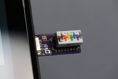
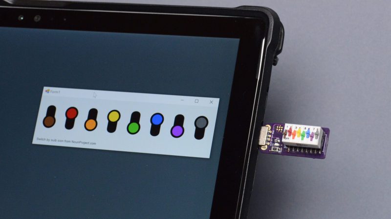
Oftentimes, when programming, we’ll put configuration switches into a config file in order to control the behaviour of our code. However, having to regularly open a text editor to make changes can be a pain. This colorful little DIP switch dongle from [Glen Aikins] makes for a fun alternative solution.

The build is simple, relying on a rainbow-colored 8-pin DIP switch as the core of the project. A PIC16F1459 then reads the position of the switches, with the 8-bit microcontroller doing the job of speaking USB to the host machine. The device enumerates as a USB HID device, and reports to the host machine when queried as to the state of its 8 switches. [Glen] used a basic C# app to show a digital representation of the switches on screen changing as per the real physical DIP switch plugged into the machine.
It’s a great tool for controlling up to 8 different parameters in a program you might be working on, without having to dive into your editor to change the relevant parts. Also, it bears noting that the rainbow design is simply very fetching and a cool thing to have plugged into your computer. It’s a more serious device than [Glen’s] hilarious 4-byte “solid state drive” that we saw recently, but we love them both all the same!


So yiu can have rainbow rom with some of these DIP switches, and the project from lastweek?
It thankfully matches 1-8 classic resistor colour codes “(Better) Be Right Or Your Great Big Plan Goes (Wrong) “
politically incorrect today, but in the Navy it was “Bad Boys R*** Young Girls, But Violet Gives Willingly” …don’t hate me, it was a different world 50 years ago…
In comms I had to learn a lot of different color codes for things like cabling and many of the old color codes for capacitors and inductors.
I learnt the resistor color code as Black, Brown, Red, Orange, Yellow, Green, Blue, Purple, Grey, White.
It’s better to learn it this way as there is not a double conversion like, Black starts with “B” so it’s first in the rhyme “Big ….”, so It’s “0”.
Without learning the double conversion you see yellow and think “4”. It’s much easier.
This feels like it would lend itself nicely to being part of a really small resistance box.
First thought: Heck, yeah! Cool idea.
Second thought: Brain hurts. Can’t figure out how to wire that to work at all.
Wire each switch in parallel with a resistor. Wrap the top of one switch/R pair to the bottom of the other. Switch in one direction, current must flow through resistor. Other direction, current shorts around resistor. This project already has inline resistors for each switch, it’d just be a matter of some simple trace re-routing and selecting whatever resistor values you’d like on it.
Sure, but try to figure out how to make the net resistor value equal to the resistor color code on the switch.
Neat. The price of those rainbow dip switches is more than what I paid for a backlit LCD. It’s amazing how economies of scale work in this industry.
Clever use of colour, guess he couldn’t resist.
I don’t have my glasses handy. They use resistor color codes, no?
Yeah, Seems I’ve exceeded my free limit of twitter and need to create an account.
This project looked interesting, It’s a pity there is no like to the project outside twitter. I mean!, no one seriously uses twitter to post an entire project. I was wondering if the switches … oh never mind.
And I only go to twitter on links from hackaday. So hey, hackaday, you’ve exceeded the maximum number of links to twitter.
Luckily they also documented their project on a good old-fashioned blog:
https://bikerglen.com/blog/building-a-dip-switch-usb-stick-using-the-microchip-pic16f1459/
The dip switches made by that company are good in every way except for one thing. One of them is the price.
It would be very extravagant to use that dip switch where you can’t see it.
These switches are beautiful. Too bad they’re so expensive, otherwise I’d use them everywhere.
8 bits? Seriously? And no parity?
Well… up to 2^8 behaviors.
that’s assuming only one behavior at a time.
Why not make it a USB drive? It could have a single file called config.ini (or something), with a single [options] section with 8 options in it. Each one can be 0 or 1.
Then in your application, open d:\config.ini and parse the options. Every time you read the file you get the current state of the switches as options for your program.
+1
I tried this. Windows and Mac both cache reads from USB mass storage devices. The first time you read the file, you get the state of the switches. The next time you read the file, you get the cached state of the switches. The only way to tell the OS that the switch state changed is to do a soft detach followed by a re-attach. This results in annoying unsafe eject / new file explorer windows / alert tones / etc every time the switch is changed. I decided to stick with good old trusty vendor-defined USB HID.
I’m a colorblind conservative, so I prefer black and white.
$10 for the DIP switch seems a bit exessive: https://www.newark.com/erg-components/sds-8-014/dip-switch-8-spst-co-slide-1a/dp/08WX5542
About $3 on eBay, if you’re willing to buy 35 – https://www.ebay.com/itm/143838078454
Biggest advantage over config files that I see is: you won’t forget the save the file you edited. I can’t tell you how many hours I’ve wasted tracking down “bugs” because I forgot to save the configuration file.
My first machine was a PDP-8, front panel switches were accessible from programming languages. I used them to turn debug routines on,off. Happy days are here again.
Buy plain old 10-button DIP switches and use markers to color them. Now make your resistance substitution box.
lol. I bought an 8 pack of (Merican brand) Sharpie permanent markers and they the right colours but missing grey and white. ie Black, Brown, Red, Orange, Yellow, Green, Blue, Purple. Perfect!