It doesn’t happen all the time, but over the years we’ve noticed that once we feature a project, a number of very similar builds often find themselves in our tip line before too long. Of course, these aren’t copycats; not enough time has passed for some competitive maker to spin up their own version. No, most of the time it’s somebody else who was working on a very similar project in isolation, and who now for the first time realizes they aren’t alone.
Thanks to this phenomenon we’re happy to report that yet another 3D printable magnetic levitation switch has come to light. Developed by [famichu], this take on the concept is markedly different from what we’ve seen previously, which in a way makes the whole thing even more impressive. It’s one thing for multiple hackers to develop similar projects independently of each other, as the end goal often dictates the nature of the design itself. But here we’re seeing a project that took the same core concepts and ran in a different direction.
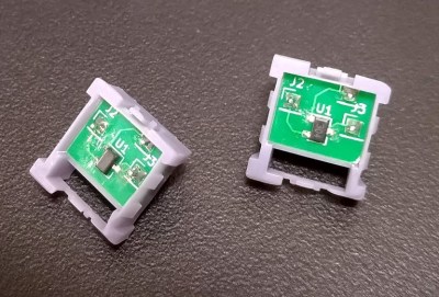
 So what makes the MagLev Switch MX different from [riskable]’s recently released void_switch? In a word, convention. It seems that [famichu] wanted to create a magnetic switch that operated in more or less the same way a traditional Cherry MX switch does, while the void_switch represents a re-imagining of how keyboard switches should work entirely. So for example, rather than putting all the Hall effect sensors on the main PCB so there’s no need to make an electrical connection to each individual switch, each MagLev Switch MX is pinned and must be wired together to form a matrix.
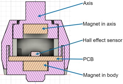
Internally, [famichu] has come up with a unique arrangement wherein the Allegro A1304 linear Hall effect sensor is actually placed in between two opposing magnets that stand in for the traditional spring. When the key is depressed the sensor will pick up the magnetic flux environment changing around it, but interestingly, the schematic for the keyboard PCB would seem to indicate that the senors are not being read directly by the microcontroller. Instead, their output is being used to trigger MOSFETs on each row of the matrix.

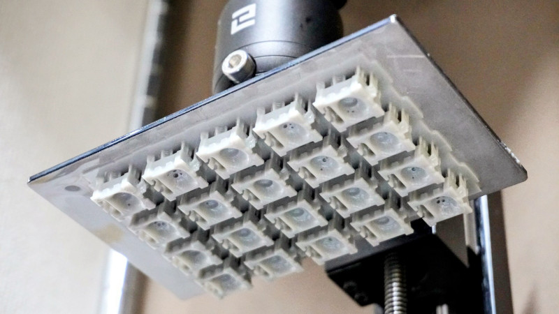
In terms of getting them printed, the MagLev Switch MX has fewer parts than the void_switch, and [famichu] recommends printing them on an MSLA machine. This greatly accelerates the printing time compared to the FDM-printed void_switch, as there’s no time penalty for filling the entire build volume of the printer for each run. As for customization, the Fusion 360 design files have been included in addition to the standard STL/3MF models. But for our money, nothing quite beats using OpenSCAD’s customizer capability for a project like this.
The big takeaway here is that there’s clearly more than one way to make an open source, 3D printable, magnetic MX-style switch. We’re very excited to see both projects develop further, especially since a little birdie tells us that [riskable] has taken a close look at this design and has a few notes to pass on to [famichu] based on his experiences developing the void_switch. With these two magnetic mavens collaborating, the future of bespoke input devices is looking very bright indeed.
Thanks to [Stephanie] for the tip.


i was wondering how this could possibly work, since my fdm printer simply isn’t repeatable enough to get satisfactory results on a part that’s supposed to slide in a sleeve…i would have to do a lot of trimming or sanding or what-not, i think. but i guess resin printing answers that question
I think most hobby level resin printers get a bit of embellishment
Slower is often your friend with this tiny intricate stuff on FDM. Its great to have a fast printer or fast print profiles for stuff that is big. But this little stuff really needs slow print speeds. Or the jerk/vibrations alone will cause serious problems. I also prefer Print outside to inside for perimeters. So that the extra ooze and stuff ends up next to the infill. Instead of the the exterior.
Also when printing tiny a smaller than the standard 0.4mm nozzle is often well worth it.
Still this level of tiny precision parts no getting around it some post processing will be needed on the FDM where the resin prints are probably smooth and dimensionally accurate (at least while new) to just work.
Calibrate your printer, dont “tune” it….
It’s almost like those two things mean basically the same thing. Crazy! ¯\_(ツ)_/¯
Very interesting. I have two high quality resin printers (one laser, one MSLA), and plenty of good resin… so I might actually give this a go. I’m working on a custom “claw grip” macro pad, and wanted something a little more esoteric, so this looks like fun. Since the github repo includes the PCB files, I might even try that method of exposing PCBs using an MSLA printer. They look simple enough I guess.
I like the fact that it’s possible to change the actuation point, would be great for not bottoming them out since I have issues with switches that don’t have tactile feedback. Trying to think of a way to add the feedback though…
Maybe Carl Bujega’s small PCB magnet projects could help. Turn the electro magnet on as soon as the output is on. I think the force won’t even need to be extremely strong to get noticed.
https://hackaday.com/2020/03/31/magnets-turn-flexible-pcb-into-electric-grasshopper/
Also has a interesting YouTube channel.
The next step is going is be very interesting: an electromagnet at the bottom, to electronically control the actuation force per key. Get enough control fast enough, and you could apply different actuation force profiles
In theory one could eliminate the need for a hall effect sensor that way, perhaps by carefully measuring the current drawn by the electromagnet.
Way above my paygrade, of course.
Make the electro-magnet strong enough and you could get the keyboard to type by itself.
Shhhh… you don’t want us programmers to lose our jobs to automation, do you?
It wouldn’t bother programmers too much. Most of the time we get paid for is compile time. Things take forever to compile. Day’s sometimes. :) Especially close to long weekends and public holidays.
It’d be a nice art project, though. Have a keyboard type out interesting historical documents over hours days.
Now need some sort of voice coil and pulse circuit to give a tactile bump when it actuates.
Appears the Allegro A1304 is made of unobtanium :(
Nice, ! Now we need compatible RGB led system !
No MOSFET and reading the sensor direct would give very useful additional data.
How far was the key pressed.
How fast was the Key pressed.
This could be used for gaming.
It would give very useful data but it also means needing to read from lots of ADCs or communicate with lots of sensors if they use i2c or anything. Using a MOSFET they can do it in a matrix like a traditional keyboard so it is much simpler and faster to get input rather than reading from potentially up to 100 ADCs.
You don’t need a zillion ADCs or a ton of analog input pins on your microcontroller. You just need some analog multiplexers (74HC4067). They can turn a single analog pin into 16 analog pins. So if you have say, a Black Pill board which has 10 analog input pins that would get you 160 analog inputs on single $5 microcontroller board.
It seems to me that using hall-effect sensors makes sense only if “analog” key sensing is desired. Otherwise the per-key parts cost would be significantly lower by going optical for keypress detection.
I’ve had some luck multiplexing 49E hall sensors by hooking their outputs up to a single ADC and powering them off separate digital IO pins. I didn’t see anything in the datasheet about unpowered behavior, but pulling the Vcc of one sensor to ground didn’t seem to have any affect on the signal coming out of another powered sensor.
This way I’m able to multiply my available ADC pins by the the digital IO pins, so long as they can supply enough current. Maybe not enough for a keyboard, but definitely useful for some designs if you want more sensors than you have ADCs.
I like the idea of it auto capping things when you type hard because you are pissed.
Musical keyboards play the notes proportionally louder when you press the keys faster.
They have one sensor near the start of travel and another near the end of travel.
In reality, most times it’s just a break change over switch. A – N.C and N.O. built into one.
The speed of the key press is calculated from the time difference and the note is proportionally louder for a faster key press. Sort of an analogue emulation.
So you could do some analogue stuff with this and you wouldn’t need a lot of resolution per key.
As there is no mechanical (force) hysteresis so you could go as far as calculating key force. Like WASD but how fast to move.
This seems overly complicated for solving wordle. All I did to cheat was import a word list into SQL, use another query to give each word a score based on which letters occur the most often in the list, then write a small JavaScript app that creates the SQL queries to return the most likely word given what I know (like letters that have to exist in certain positions, letters that have to appear in the word, letters that do not exist, etc.) then i just return them in the order of the words score.
Rarely does the JavaScript code ever have to guess more then 3 times.
I tried to make an auto solver that people could load up in their browser that would solve the puzzles for them but stopped when cross site scripting got in the way of the Iframe.
whoops wrong article… i need coffee today.
You’re not wrong though. Printing your own keys _would_ be overly complicated for solving wordle.
Now I want to make a keyboard that’s only purpose for existing is to solve Wordle 👍
If it lit up like the Wordle soft keyboard, that would be sweet. You could start with all the letters white, then turn them off or turn them green or yellow.
I prefer a good old
cat wordlist.txt| grep -E “^..a..$” | grep t | grep i | grep r
as it leaves room for interpretation of commonality
Cool!