[Electronoobs] built a coil gun and the obvious question is: how fast is the projectile? To answer it, he built a chronograph suitable for timing a bullet. The principle is straightforward. A laser and a light sensor would mark the entry and exit of the projectile over a known distance. As it turns out, there are some issues to resolve.
For one thing, a laser is too narrow and might miss the projectile. The first attempt to rectify this used mirrors, but the loss was too great — we suspect he was using a second surface mirror. The final answer was to use an array of detectors and removed the laser’s collimation lens to cover a wider area.
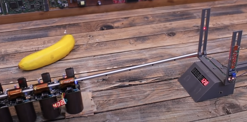
That worked, so all that was left was a nice mechanical design to allow changing the height of the sensors and the distance between the sensors. After that, an Arduino can take over.
We liked the mechanical design and the way he managed pushbuttons in the 3D printed case. We couldn’t help but wonder if a first surface mirror might have worked better. We also thought it would be nice to add some sort of encoder to let the device measure the distance between sensors automatically since it is adjustable. We also thought the response time and wavelength sensitivity of light-sensitive resistors might be a bit off. It seems like a photodiode or transistor would be more accurate and have better sensitivity to the laser or even just a conventional light source. But this does seem to work.
How fast was the coil gun? Well over 100 meters per second. For a point of reference, a .22 caliber round will have a muzzle velocity of well over 300 meters per second, but, still, 120 to 130 meters per second is nothing to sneeze at.
If you need a coilgun, we always liked the looks of this one. Or, you might prefer a more futuristic look.


But why use laser? Regular LED would not work?
Isn’t a laser without a collimator just an LED? =) I’m also not sure why he chose a laser other than that’s what everyone uses in such situations. As ROB points out down below, there are better parts to use like IR detectors, and IR LEDs are also readily available and require less effort than lasers.
nope, laser = coherent, led = not coherent
that said, a regular led would probably have worked just as well…
https://www.edmundoptics.com/contentassets/e755938df1834ad2b738f536d308cdd2/laser-la-2.gif
Winston, that gif is far less funny than I expected.
No. A laser emits light by a process called “stimulated emission”, where the photon resulting from the decay of one excited quantum state “stimualtes” another nearly identical quantum excited state to also decay, and thus lose a photon of almost the same amount of energy. When this happens, the 2nd photon is in phase with the first photon and moves in the same direction. This what is meant by the term “coherent light”. The photons coming from LEDs are not produced this way, even if the light is nearly all the same color. Because the photons in the laser have wavelengths that are nearly identical — but not a perfect match — they will begin to get noticeably out of phase with each other after traveling some distance. This distance is called the “coherence length”. The larger this distance, the narrower the bandwidth of the laser (more monochromatic). Lasers with large coherence lengths are very expensive. In gas lasers, one reason the photons have slightly different wavelengths is that the atoms emitting the light are in fast motion, so there is a small Doppler effect.
Very informative, but yet another person falls victim to ignoring the smiley. =D
Don’t want to be “that guy”, but, it might not be an optimal design decision that you have to kinda stand in the actual flight path to use the buttons and see the display. Maybe turn that part 90 degrees?
As long as it’s a one man show, I doubt he’ll shoot himself in the back, but you have a point. It looks like he could just make a couple new screw holes in the uprights’ lower horizontal arm, and maybe extend a few wires a bit and not have to reprint everything. Whether the result will be worth the effort is the only problem. For anyone wanting to recreate the design, it’s certainly something to keep in mind.
The layout is standard for chronographs. With the display on the front the shooter can read the measurements after each shot without having to step past the line of fire or have the assistance of a second person. If the display is on the side then you either can’t get feedback from the chronograph until you stop shooting and make the gun safe, or you have a second person standing past the line of fire while the range is hot which no range officer will permit.
You have to break the 180 degree rule to get to the chronograph to begin with. It doesn’t matter where the controls are oriented. The display should definitely be pointed towards the shooter though, it can be read from behind the firing line.
I doubt that this is very accurate.
LDRs have a slow response. On top of that he is adjusting a 270 degree pot (not ten turn) pot for a threshold and there is a time between the bullet passing and then a time before the LDR resistance goes higher (2 – 50 ms) and a time delay before it reaches each of the different voltage thresholds of the separate adjustments. And all of this based in the precision of using an ordinary ruler to measure a distance of only about 200 – 300mm.
I’d probably go with a distance of 2 to 3 meters and use IR or UV detectors and perhaps try a light trapezoid (rectangle) so that the same sensor is interrupted at both ends instead of separate sensors.
I have seen lasers that put out a line of light and that may be the way to go. Along with some mirrors … and perhaps smoke for additional effect.
If his design allows for the same timing and threshold errors on each detector then the errors would cancel out and the result would be valid. If you knew that you had a consistent repeatable velocity then that could be achieved by swapping the sensor assemblies a few times whilst taking measurements. Calibrate until you get the same readings regardless of which way around they are.
I doubt that he has a repeatable velocity though, so he’s in a bit of a chicken and egg situation. He might be able to create a calibration rig with better repeatability – e.g. a mains line frequency synchronous motor driving a slotted disc.
Simpler, just pulse both LEDs in parallel using your choice of 555/arduino/RC-driven double inverter oscillator and analyze the responses using a 2-channel oscilloscope. It’s probable that the LDRs are not very precise, so he’d want to characterize them individually out-of-circuit and select the two closest examples. That could be achieved using any benchtop power supply that has current control to drive the LED whilst measuring the LDRs’ responses. The LEDs themselves are likely to be consistent enough, but they too could be matched if necessary.
Common-mode error rejection is used in many measurement techniques – it’s often not as important to get zero errors in the sensor data as it is to get the same errors so that they can be canceled out. Here he doesn’t care if the sensing circuits trigger 20ms late, as long as both trigger repeatably 20ms late.
The easiest way to cancel error by having the same error from both sensors is to just use one sensor for both events with a more complex light path.
Another way would be to have a ruler behind the projectile and a very fast LED strobe and a long exposure picture but I don’t think that would help with modern cheap cameras because of the scan progression rate being too low. It would work with film.
You could use a single light source (something fast on and off like a LAZER) and strobe it just for calibration. Adjust the sensors so they trigger at the same time. It could be tested with a simple DQ flip flop.
It depends on what he has on hand.
Don’t trust mains line frequency. It’s adjusted to compensate for load throughout the day.
True, but the variation within any given second is minute. Within any single revolution of the disc you’d be unlikely to see any significant effect from that, so the principle used here would still work.
It would be simpler to suspend the thing (or simpler, a piece of wood) from a string or two, and let the bullet hit it. Measure how far the pendulum swings. From the mass of the pendulum and the bullet, calculate the velocity of the bullet. The good old ballistic pendulum.
I wonder how hard it would be to pick up the sound of the gun firing, then the sound of the projectile impacting over a known distance and work it all out from there.
Definitely not accurate enough. Sound propagates at different speeds based on humidity, temperature, elevation. Too many variables. Also you’d have to be hitting something like a steel target to get any real sound out of the impact.
I used some software years ago that did this. It listened for the bullet leaving the barrel and the bullet hitting the target. The mic was placed half way down range to cancel out the speed of sound problem. This was for a sub-sonic pellet gun. From what I remember is worked well. And the only hardware you needed was a computer and microphone.
I’m skeptical of the accuracy. 130m/s is very fast for a coilgun, and his design is far from optimal.
Agree, doubt it’s accurate. Even with optimal design deviations are pretty high.
Couldn’t one just use two coils and look at the time difference in the induced EMF?
That would work but it’s a bit analogue now days. You need to pick the same point in the EMF signals at both points. The obvious place is the end of the rise and start of the fall. So a capacitor into an open gain op-amp but like I said that’s probably too analogue.
The coils wouldn’t need to be much either because of the speed. Even sensing the eddy currents would be enough.
one approach for signals of varying size but similar shape is to
use a peak hold circuit then divide by 2 and trigger a comparator with this signal on the falling edge
this removes the jitter present when a fixed trigger threshold is used on the leading edge.
its also somewhat insensitive to inaccuracies in the circuit implementation so long as they are consistent between shots
Personally I would just sample it continuously with a microcontroller .
Even a modestly humble microcontroller tends to have a 10-12 bit ADC able to sample in the low MS/s. And most have inbuilt muxes as well, so that one can scale that one ADC out to multiple channels, sometimes to near silly degrees, but we only need 2.
This will though mean that might only sample at a 1 million times per second. Or for a projectile traveling at 1km/s between two coils spaced a meter apart, we suddenly have 1k samples of waiting for the other signal from when the first appeared.
And we don’t have to worry too much about wasting a ton of processing power on sampling, even a slow microcontroller will have plenty of extra grunt available.
You could use a combination.
Monitor the ADC until the signal is rising and well above noise levels and then enable interrupts.
Have the signal capacitively fed to an open loop gain inverting op-amp that outputs close to 0 Volts for rising signal and almost Vcc for falling signal. Use positive edge of that to trigger an interrupt and take a sample of the time high speed counter then disable interrupts.
Repeat for the second sample and take the difference between the two counter reading to calculate time and divide the measured distance by the time for speed.
“Have the signal capacitively fed to an open loop gain inverting op-amp that outputs close to 0 Volts for rising signal and almost Vcc for falling signal.” Seems like a waste of components to be fair.
This is after all a trivial measurement that any micro with 2 ADC channels should be able to do.
When coil A moves outside of our noise threshold, be it positive or negative, then we start a counter.
Then we timestamp when coil A returns within the noise threshold. (preferably add a hold off delay before we consider this valid as to not struggle with noise.)
Then we timestamp when coil B moves outside our noise threshold and timestamp when it returns.
Then just take the average time of our two timestamps for coil B and subtract half of the timestamp we took for coil A. Then we just need a conversion factor for converting this time into speed.
Most ADCs in microcontrollers have fairly decent input impedance, so it is debatable if one even needs a preamp.
Perhaps on some uC’s it’s trivial but not all.
The time between the two pulses is 140us and that’s not a lot of time to be waiting for a successive approximation ADC to resolve on lower end uC’s.
Sure some uC’s will have a comparator but some won’t.
Then there’s the repeatability issue. There is exactly one moment that a signal goes from rising to falling even if it’s rising for a (relatively) long time and falling for a long time.
The transition is level independent.
Using an open loop gain op-amp to a digital IO and triggering an interrupt from that give repeatable results without any adjustment. You just have to keep the Interrupt Service Routine short and make suer there is enough time for the first ISR to complete before the second iteration.
It would probably even work on an 16MHz Arduino ATmega328p.
“There is exactly one moment that a signal goes from rising to falling” not when there is noise in a system. And a large coil tends to pick up a lot of junk EMI.
The ATmega328p has a very slow sampling rate at only 15 kS/s, it really wouldn’t be a micro to pick if one were to take the approach I suggested. The PIC32MX is a lot more suitable for the job. (though at twice the price, but with a lot more features.)
A project like this measuring the speed of a projectile using the on chip ADC is a decent hello world project if one picks up a larger micro capable of doing it. Since it does throw in a few nifty issues that isn’t always obvious at first glance.
Btw, I am not against using external components to do the job as well. One could even do it with a set of 555 timers and a panel meter and simply accumulate how long it took for the projectile to travel through, store that accumulated value in a capacitor and buffer that out to the panel meter with an op amp, would need a pot to calibrate it though, and a high speed reference.
There is so to say many ways to skin our coil sensing cat.
But if I were out in a field in real life doing a measurement like this. I would just bring an oscilloscope.
Err… um.., you just can’t say .22 caliber round, you need to be more specific. A 22LR round flies at around 1200 feet per second, a .223 round (still a .22 caliber bullet) flies at around 3100 fps. Please be a little more specific, some of us shooters are looking at this for our range time.
When someone says .22 caliber, they mean .22 long rifle. Technically speaking, a .223 isn’t a .22 caliber round anyway, it’s a .224 caliber bullet. Nominal vs actual size and all. Anyway, if you actually shoot guns you should know that people call .22LR .22, if you don’t know that, you’re probably a poser.
This is true. I’ve shot guns since I was probably 7 years old or something. I can hit pretty much anything I want from any distance I can still see or imagine seeing. I can shoot carpenter bees out of the air with a BB gun. However, I don’t know all the terminology and bullet size specifics. I know that when I was growing up we had a .22 that could shoot shorts or longs, and a .22 6 shooter that could shoot shorts but not longs (I think), and we never bothered with .223 or .224. What’s my point here? Some people shoot as a hobby and really get into the specs and gear. Some people shoot culturally and don’t bother with all the specs and special terminology. Both can be great shooters, but for people who grew up shooting, sometimes that stuff doesn’t matter.
Absolutely. Not to mention the .22 short and the 22LR high velocity rounds. .22 caliber air/pellet guns are also common. There’s a bit of diversity in the .22 department.
In my country .22 just mean the normal .22 bullet that would only go so far and then seeming fall strait to the ground. Then we had what we called “shorts” which were used for things like target practice where they didn’t have to travel far. The we had “longs” or more commonly called “long range” .22s that had a longer shell and more powder.
Assuming he’s using metallic projectiles, would a Hall effect sensor be possible here? Seems like as long as it’s sufficiently sensitive and calibrated to the environment, it could offer very responsive measurements.
With no hot expanding gases in the barrel, why not just mount two lasers pointing through the barrel a set distance apart and have the speed show up on the coil gun’s LCD display?
That’s a good idea. If you have the laser pointing through the barrel, you’d also get a dot at whatever you’re going to shoot at until you load the chamber. Then as it speeds away, you could measure the distance of the projectile at known times and calculate the speed that way.
While it’s fun to build your own chronograph, ready made ones are very inexpensive. A Caldwell Ballistic Precision Chronograph is $75 at Midway, and a PACT Mark 7 Sky Screen System is $70. You can also get MagnetoSpeed Sporter Chronograph for around $180, that attaches directly to the barrel. I haven’t look deeply into those, so I don’t know if they’re Hall effect, an RF field, or what. I do know they’re not optical.
Nice work as I have everything here I will be building this chrono, my only change the laser I have many line lasers available which will make project even simpler!
Electronoobs’ coil gun is impressive, hitting over 100 m/s—quite the speed! For comparison, a .22 caliber (https://gunsnprices.com/ammo/rimfire-ammo/22-lr) round clocks in at over 300 m/s, so while not as fast, the coil gun’s performance is still noteworthy. The chronograph setup with lasers and sensors was clever, though I agree, using photodiodes or transistors might improve accuracy.