Although powerful design software and cheap manufacturing services have made rolling your own PCBs easier than ever, there are some situations where a piece of FR-4 just doesn’t cut it: think art projects with hidden LEDs or biomedical applications that need to attach to the human body. For such occasions, [Narjes Pourjafarian] and her team at Saarland University in Germany developed Print-a-Sketch: a handheld device that lets you print electric circuits on almost any surface using conductive ink. Also check out their academic paper (PDF).
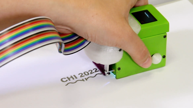
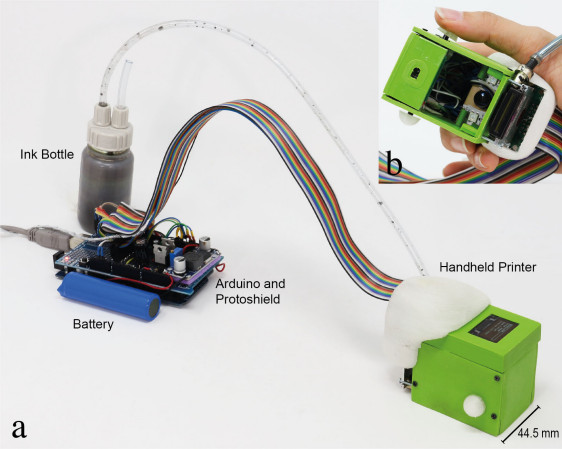
The heart of the device is a piezoelectric print head, as used in some types of inkjet printer. It dispenses tiny droplets of silver nanoparticle ink, which is conductive enough to make useful electronic circuits by simply printing a schematic. Lines can be drawn to connect components, while customized footprints can hold LEDs, capacitors or even integrated circuits.
 As demonstrated in the video embedded below, the Print-a-Sketch can be used in various different modes. In freehand mode, you can draw whatever you like just by moving the device around. But it also has several assisted sketching modes, where it can straighten out wobbly lines, draw multiple lines in parallel, or even print complete predefined shapes. Especially satisfying is the way it can draw resistors by literally printing zig-zagging lines.
Thanks to an optical motion sensor, similar to the ones used in gaming mice, the device knows at all times where it is and how fast it’s going. That enables the control circuitry to compensate for unsteady movement; the authors claim a printing precision of less than 0.5 mm. In addition, an RGB camera is used to detect the material underneath and adjust the amount of ink dispensed, depending on how absorbent the surface is: rough paper needs more ink to obtain a conductive trace than a ceramic tile.
The number of potential applications seems limitless: how about a yoga mat with integrated touch buttons to control the video player on your iPad? A piece of kinesiology tape with an integrated stretch sensor to measure the exact motion of your arm? Or a floor tile with a printed moisture sensor? All of these are demonstrated by the team, but we’re sure our readers can come up with many more ideas.
Of course, drawing circuits using conductive ink is not a new idea: previous projects either relied on drawing the entire thing by hand, or used traditional inkjet printers. But the Print-a-Sketch’s sophisticated hardware and software really put it in a league of its own. And since the entire design is open-source, you can simply build one and bring your ideas to life.


It’s neat but the print head it uses is several hundred dollars
This is a great idea. I want to know more about the print head and resolution. I’m dreaming of an Open Source 2D printer that can be placed as tool head on a multi head 3D printer, and the is a great starting point.
The mild stopping point is $500 print head.
https://info.digiprint-supplies.com/hubfs/xaar-128-datasheet-eng7.pdf
That’s a sparse datasheet!
I think it was 125 Euro for the printehead. Its by Xaar. We should have source code online if you go to our website.
I was looking for something to print conductive ink on a larger surface (40*30cm) and seems like this would exactly fit my use case. But after checking the price of just the printhead (3000$) I think this project won’t be the next one that I’ll work on.
Actually you can find the printhead for under US$300 from many sources including: https://us.digiprint-supplies.com/en/xaar-128-80w-pphxa128pt. But still, not cheap.
This reminds me of the Data Pen input device.
It used a scroll wheel and a very tiny, for the period, camera. It used to plug into a parallel port and had batteries on the cable connector. It was essentially the inverse of this but for text reading. It was largely awful, it’s amazing how much technology has moved on.
I had this, or something very much like it in high school. You could scroll it over text as though it were a highlighter, and it would scan and save the line. From there, it could save passages to refer to later (and transfer to the PC for note taking), read the text out loud, or give definitions. It was clunky and outdated when I got it, but it was (and in my opinion, still is) a pretty awesome piece of technology!
This is fake!
If you look at the parts where it adds something to an already existing trace, you can always se a small glitch in the video from the cutting.
I guess they just draw/printed the traces before. Then put the “device” over the already printed trace and moved it to the right.
Also the trace is never longer as the are the device can cover since that would need an additional cutting of the video.
Very interesting observation gde! At first I thought you were crazy, but after looking at each spot involving existing traces there is a weird jump cut at every last one of them. It’s very obvious with thumb placement as it’s never 100% the same. A couple of times it looks like they might be holding down the button with their thumb and then releasing it, but you never actually see the release motion it just jumps. Very interesting indeed.
But it cannot be… with a corporate soundtrack like that, it’s gotta be inspiring and awesome and “introducing:”-ed in all kinds of ways.
Sadly I’m inclined to agree with you. This sort of tech should definitely be doable. There’s the handheld router that can adjust your cuts on the fly, but it uses marked tape to know where to do what and it steers you in the right direction on top of that. I’m afraid this video is only going to cause problems for the people involved. That much editing alone is enough to raise questions. The music and voice make me think this is more of a marketing experiment than an engineering one. Perhaps they could release a video with NO editing showing the same things, and remove all doubt, but that probably won’t happen anytime soon.
I found the source on github. It was on the university project page which was linked in the pdf that’s available from the link in the article. A bit buried, but we should be able to get some idea of whether or not this actually works by looking at the code.
https://github.com/HCI-Lab-Saarland/Print-A-Sketch
I looked through the code. I’d say there are some lies, and some possible truths. I don’t see ANY code for scanning anything and printing that out on the fly. All images are hardcoded in the firmware and it seems can be selected. Lines are possible. It has jitter control to keep the lines straight. It has the mouse sensor to track x and y data, but again, I don’t see anything about the ability to scan components or drawings. I didn’t see anything that can scan or see previously printed lines. Without having it in hand, I’d say it can print a straight line or print a hardcoded image. That’s all.
The RGB camera is also absent from the schematic they have on github. https://github.com/HCI-Lab-Saarland/Print-A-Sketch/blob/main/Print-A-Sketch_Schematic.png
My last thought: I think the RGB stuff might have been added on later or taken off the end design, because what’s doing the image recognition/manipulation computations? An ATMEGA? I doubt it. Not if you want it to be done on the fly as described. Maybe you could get it to find some edges in high contrast low resolution images, but that’s not what’s described in the paper. The paper and the project as it is now on github are very different. I also didn’t see the material lookup table in the code that was described by the paper, but I might have just missed it. Anyway, let me know if I overlooked anything. I’ll happily apologize, retract, qualify, or modify any statement I’ve made in error.
Ok, my really real last thought: The focal distance on that camera in the picture is too short. It would always be blurry unless it is a macro lens, then it wouldn’t fit an entire 555 (or whatever that chip was) in frame without moving the device around as a scanner. I bet this is why they didn’t include any of this in the ACTUAL device, only in the marketing. It sounds nice, but in practice would be insanely expensive or impossible with current tech unless you could somehow fix the component to the surface and move the mouse around to scan the whole thing. Then you’re still working with an underpowered MEGA to try and stitch all those images back together. I’m just not seeing it happen.
You are right with some of your analysis. The RGB stuff is done on a computer, not on the Atmega. A python script analysis images and updates the data-stream that is being sent to the Atmega (and from the Atmega to the printhead).
I believe only the embedded stuff is open-sourced, as we figured this would be what might be most useful to others (so you can use that to build your own hand-held or CNC based inkjet-printing devices).
Lines are short, because the conductive ink is not super easy to get a hold of, so we didn’t want to waste any.
Its a prototype, a proof of concept, not a product.
I can understand all of that except the part about it not being a product. You’re selling it much harder than you’re sharing it. Smells like a product. Maybe you’re selling the people, maybe the school. Something is definitely being sold.
Not exacly in the same subjet as you but you will also like the 5x time speed. Not exacly fast.
I love the feature which scans an SMD part and then prints the pads. Very cool. Lots of great thinking went into the software features. Much more than just a handheld printer.
Seems like it would lack the durability for many of those uses.
If it can‘t print 3 strictly perpendicular lines it is useless!
How exactly would you draw three strictly perpendicular lines on a two dimensional surface?
Simply by making it, in color – transparent green works best.
You are welcome.
Preferably in a form of a kitten
How to you attach components? Conductive glue?
If you know the dielectric constant for ceramic tile (or Perspex) you should be able to print RF stripline layouts.
I’d like to see a filter printed on assorted materials, and then compared using a decent network analyser.
And how precisely will I moutn through hole parts to these sketches? I think I’ll stick with FR4.
Wonderful The people developed this deserve to be rewarded and make a good profit.😄
It’s a cool build, but a shame that the printhead has such a high price point. Piles of discarded office printers is a normal sight where I live because it’s cheaper to buy a new printer than filling it up with ink. So being able to use one of those perfectly fine throw-away printheads would have been a fantastic hack