84 years ago, a teenager built a TV set in a basement in Hammond, Indiana. The teen was a radio amateur, [John Anderson W9YEI], and since it was the late 1930s the set was a unique build — one of very few in existence built to catch one of the first experimental TV transmitters on air at the time, W9XZV in Chicago. We know about it because of its mention in a 1973 talk radio show, and because that gave a tantalizing description it’s caught the interest of [Bill Meara, N2CQR]. He’s tracking down whatever details he can find through a series of blog posts, and though he’s found a lot of fascinating stuff about early TV sets he’s making a plea for more. Any TV set in the late ’30s was worthy of note, so is there anyone else out there who has a story about this one?
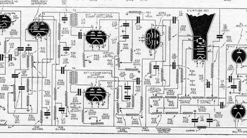
 The set itself was described as an aluminium chassis with a tiny 1″ CRT, something which for a 1930s experimenter would have been an expensive and exotic part. He’s found details of a contemporary set published in a magazine, and looking at its circuit diagram we were immediately struck by how relatively simple the circuit of an electrostatically-deflected TV is. Its tuned radio frequency (TRF) radio front end is definitely archaic, but something that probably made some sense in 1939 when there was only a single channel to be received. We hope that [Bill] manages to turn up more information.
We’ve covered some early TV work here not so long ago, but if you fancy a go yourself it’s not yet too late to join the party.


Oh great, so we’re blaming the ‘boob tube’ on radio amateurs now? LOL
This is beyond very cool. Thank you.
Something like that is more likely to get a write-up in an amateur magazine or bulletin, and copies would have been kept by the relatives of this person, perhaps also letters. I’ve got antique Fotofacts but those are for commercial models subsequent to TV’s experimental stage. His friends, relatives, hobby people would be your best bet for this kind of thing.
I have spent most of my life thinking the rectangle vs. zigzag resistor symbol is a US vs. UK thing. Now I see that is not so, as that article with its zigzag resistors is definitely not UK-derived: it mentions 60Hz refresh rate. So maybe it is time to stop doggedly sticking to my zigzag resistors marking myself out as an old dinosaur!
Interesting. I always thought the strange zigzag resistor was a) an American thing b) a relic c) a special symbol for carbon resistor. I’m from Europe/Germany, by the way. Hopefully, I’m not embarrassing my fellow countrymen by telling this. 😅
Contrary to that I always assumed the zigzag idea came from a wire-wound resistor!
You’re right, that makes sense. Thanks for pointing that out.
My father still has some resistance wire in his shack, I believe.
Somehow I must have had been associating carbon resistors for being the most basic resistors (vs metal film resistors).
Another traditional difference might be the transistor symbol, I guess.
We’re drawing it with a circle and different letters are used for different transistor tasks. Say, T, TR or Q.. Very confusing sometimes. Also seems to be a generation thing, not sure.
The circle is a tribute to the tube era, I suppose?
Zigzag is for hand-drawn resistors. Rectangle is for resistors drawn on a draughting table. These days you can choose either with yer fancy CAD tools.
I was thinking the same, but according to Wikipedia, zig-zag is ANSI symbol, while rectangle is IEC symbol. So, again Us vs rest of the world. :-)
Yes, because Europeans are neater.
It’s from the days of hand made components.
Want a resistor get a metal or carbon rod and filing a “V” into it. When you get close to the desired resistance then stop with that “V” because a small increase in filing can be a significant difference in resistance. Instead start a second “V” as you can file more for less change in resistance, finish with a third for precision and you end up with \/\/.
Same with the diode symbol. In the early days you had a connector pointing at a plate with the crystal (germanium) in between. You would have to keep “adjusting” the diode contact because of oxidization so the plate was fairly large so that that you didn’t accidental flick the crystal off and that is were the diode symbol came from.
Well later ones, the diodes in the above schematic, one is very unhappy and the other is a Cylon. lol – tube symbols are just what’s in the glass envelope.
Capacitor – two plates of metal close together. etc etc If we started electronics earlier we would have symbols of axes and clubs.
Ah, yes. The crystal “detector”. My father still has a few true vintage detectors. Ironically, if properly adjusted, they have better specs than modern glass diodes. Haven’t expected this to be honest.
Contact the Valparaiso Technical Institute to access their museum of electronics. They have everything from early telegraphs to today. Although the school no longer exists, I believe that the museum is still there in storage.
The sircle represented the tube’s envelope, and was carried over into the transistor era. I guess people decided drawing a circle around a transistor was a waste of effort, so the practice was generally discontinued. However, it may still have some value respresenting dual transistors.
In a diagram otherwise filled with only horizontal and vertical lines, the circles certainly serve to visually highlight the active elements of the circuit – be they tubes or transistors.
But if you look at some of the variations in the depictions of tubes’ internals, which can easily run to a dozen elements, my guess is that the circles were used literally to “round up” all those pieces.
I still see transistor circles in most of the schematics I see so I am curious now if this is a regional thing?
It still has valuable meaning. The circle shows that a Darling transistor is two transistors and two resistors in one package. The circle can show a diode is internal on a BJT or FET. I see circles around LEDs and still commonly, normal diodes.
It’s interesting that this guys is looking for info on a 1” tv screen. As it turns out, this months issue of Nuts and Volts describes building a 1” oscilloscope based on a 1960s article. https://www.nutsvolts.com/magazine/article/build-a-one-inch-scope?utm_medium=email&_hsmi=210165098&_hsenc=p2ANqtz-9d1F4oDSTizSbg5LgxpjFjqACP04jP74EU_HX39PaLA2LpzgQ9qhY9CSGrsc4Kof4D9dZULC8wrx3T7LjVoP5d7ElTyA&utm_content=210165098&utm_source=hs_email
The article uses a slightly updated tube circuit. It looks like a cool build and described obtaining the crt from the UK on eBay.
As for viewing a tv picture on a small crt, I remember viewing a tv picture using a microscope at the Seattle worlds fair in 1962. I was 9 at the time and it made a huge impression along with the other wiz bang stuff on display there. I think it was at the RCA exhibit along with the chance to see yourself on TV. I’m not sure what good it was but it was neat. Another impressive pavilion was the atomic energy commission pavilion where they would make your silver dime radioactive. It would pass by a nuclear source, become radio active and then they would put it in a plastic case and give it back to you. You can still find these dimes for sale on eBay.
Holy half-life, Batman!
I’m glad the discussion eventually got back to the TV. Slow-scan TV DXing has always been the purview of radio amateurs, and I still think that old documentation on this particular device would have been the subject of discussion in that arena.
Unfortunately a lot of these experimental projects got torn apart and the components reused for new experiments like we all do. Remember that back then electronic components were considerably more expensive than they are today in terms of relative pricing. Back in the day I tore down a lot of junk (today’s “vintage”) stuff and reused parts.
That’s how I started as a child. Old stuff people were throwing out was my only parts supply. But it wasn’t for being poor, I did manual tasks for various people (mostly older people) for money on weekends like lawn mowing working at various places but there was no where I could buy a component in my remote town.
It’s a constraint that created a lot of “creativity” is using parts in ways that they weren’t intended to be used but are quite effective.
ROB, a lot of people started that way, rich or poor, because it was a great learning experience. Make note of your experience, put that on an island under an embargo and you have Cuba, home of one of the world’s most notorious junkyard genius that wound up masterminding and running Radio Havana: Arnaldo Coro. Translate that to keeping vintage cars always running, and you have junkyard geniuses all over Cuba’s roads. Yours is actually a noble background.
We have reached some conclusions about this project:
https://soldersmoke.blogspot.com/2022/04/conclusions-about-w9yeis-early-1940.html