Some people state that ESP8266 is tolerant of 5 V logic levels on its GPIOs, while others vehemently disagree, pointing at the datasheet-stated 3.6 V maximum. Datasheets aren’t source code for compiling the chip, however, and aren’t universally correct and complete either. [Avian] decided to dig deeper into the claims, conduct an experiment with an actual ESP8266 chip, then share the results for all of us.
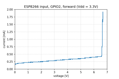
For the experiment, he used a curve tracer – a device capable of producing a wide range of voltages and measuring the current being consumed, then plotting the voltage-to-current relationship. This helps characterize all sorts of variables, from diode breakdown voltages to transistor characteristics. The curve tracer he uses is a capable and professional-looking DIY build of his, and arguably, deserves a separate write-up!
The reasoning behind [Avian]’s experiment is simple – if the pin, set to an input, starts consuming a higher amount of current at a certain voltage threshold, then there’s gotta be some chip-internal structure, intended or unintended, that would be damaged at this voltage. Curve tracer in hand, he set up an ESP-01 module to set a GPIO to input, and started increasing the voltage.
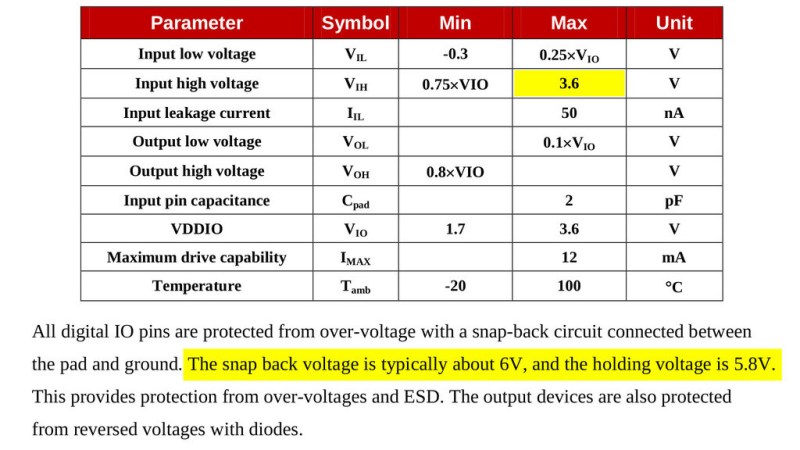
The tests have shown that, while there’s a reverse biased ESD diode from GPIO pins to ground, there don’t seem to be diodes from the GPIO pin to the VCC rail – and those are the primary concern for 5 V tolerance. There does seem to be something functionally akin to a 6 V Zener diode internally, which should clamp the voltage before it gets too way high for the chip to handle. None of that should be a problem for 5 V compatibility, and it seems fair to interpret this as a confirmation of 5 V tolerance until someone shows otherwise.
[Avian] didn’t want to destroy an ESP8266, so the experiment was conducted with a 1 K series resistor between the curve tracer and the input – which might have biased the results a bit. On the other hand, adding series resistors in front of your inputs is an overall underappreciated practice, 5 V or otherwise. He also points out that, while the pins don’t seem to be adversely impacted by the higher input voltage, the bootloader might set some of them to 3.3 V outputs on boot-up, shorting your 5 V source to your 3.3 V rail — worth keeping in mind!
[Avian]’s research journeys are fun to follow, and we recommend you check his blog out; last time, we covered his research of an innocent-looking 3.5 mm jack hiding a devious audio compensation circuit. Since we first covered the ESP8266 in 2014, we’ve been researching all the things it’s really capable of, and we brought up the topic of GPIO 5 V compatibility way back in 2016 – it’s reassuring to finally put this question to rest!
We thank [Adrian] for sharing this with us!


If in doubt – ask Hackaday: https://hackaday.com/2016/07/28/ask-hackaday-is-the-esp8266-5v-tolerant/
I will reiterate to the first comment on that post: “Just because some parts are…”
3.6V is the guaranteed tolerance. A change in process, a marginal fab run, any number of other things, can bring a particular part down to the line with no warning, and at the limits of performance (temperature, and so on) the tolerance may degrade. Many, many people have been burned by manufacturers sticking to the data sheet spec rather than past parameters
Many people have “burned” themselves by relying on observed behavior rather than the datasheet promised behavior.
Design by the datasheet, not by “well, it works for me.”
Then again, many more have burned themselves by relying on datasheet promised behavior rather than the observed behavior, when the datasheet turned to be wrong or outright lying.
Not trusting the observed reality, instead choosing to trust the printed word, doesn’t seem very sane to me.
I’ve twice had to deal with half-assed circuits someone else designed that depended on observed behavior rather than datasheet promised behavior.
In one case, it was a CMOS circuit as an interface between a 9V logic system and a 5V logic system. The guy who designed the circuit just assumed that the CMOS parts would recognize a 5V high as a high. The parts he had in stock happened to to that. After the prototype was built and tested, the company made a whole bunch of them for a customer project. Surprise! None of the new boards worked. The datasheet specified something like 6 or 7 V for the minimum voltage of logic high. Some production runs will accept 5V, some won’t. I got to root through all our stocks looking for ICs that would accept a 5V high so that we could make the first delivery. The design was changed for later deliveries.
The second case was more like what we’re talking about with the ESP8266. I worked in a factory building 2-way radios. One particular model could be put into factory test mode by pulling up a certain pin on the external conenctor at power on. The was a 74 something series IC that latched that input. It was a 5V part. One day, all the new radios coming out of production quit going into test mode. I got stuck with figuring out why. They all worked on my test rig, so I compared it to the workplaces where radios wouldn’t go into test mode. It turns out that all the other test rigs were using a pull up to 12V instead of the proper 5V like my test rig. All the ICs that had previously been installed tolerated the 12V on the input. The new ones didn’t – they locked up rather than switching to test mode. The other rigs used 12V because there was a 12V pin right next to the test mode pin – there was an SMD 1202 part soldered to the pins. My test rig used a proper 5V source for the pull up. We got the technicians to install the correct pull ups on the other test rigs, and all was good.
Trusting “works for me” rather than the printed word “doesn’t sound very sane to me.”
If you work from the datasheet and its wrong, then that’s the manufacturer’s fault.
If you go by observed behavior and it quits working, that’s your fault.
I had to bodge together a do-dad one time that took input from a number of industrial sensors and report it to a PC. I cheaped out and just clipped the voltage going to an AVR with some Zener diodes … what I failed to notice was the 4.7 volt diodes I used were actually 47 volt, thus doing nothing and passing the 24 volt output of the sensors directly in the inputs of the AVR
Worked great, that must mean AVR’s are 24 volt tolerant right? … until a few weeks later it didnt work at all and I found my mistake
“Then again, many more have burned themselves by relying on datasheet promised behavior rather than the observed behavior, when the datasheet turned to be wrong or outright lying.”
The datasheet doesn’t say that the device will burn from 3.6V to 5V. It just says it’s guaranteed to work from an input high voltage of 0.75VIO to 3.6V.
If the device works above 3.6V, that’s not the datasheet lying. The datasheet lying would be if it didn’t work between 0.75VIO to 3.6V. The datasheet literally says nothing about the device’s behavior with values outside of that range.
Observations only apply to one part. Datasheets apply to every part of that model, unless they are defective(Because the datasheet is the definition of what a good or defective part will do).
If you can’t rely on published specs, can you trust the part at all?
Sure, you can do your own testing, but you don’t know if they will change things and not tell you, since you couldn’t trust them to have accurate data to begin with.
It might sometimes be necessary but it’s not ideal.
FWIW when we write datasheets, we have a recommended operations specification and an absolute max voltage specification, and include the warning that operation for extended periods outside the recommended voltage range may result in lower reliability or unexpected operation.
For instance, in internal testing, operating at above the rated voltage at higher or lower than room temperature often results in failure of the pin ESD structure.
Based on what we see in customer returns, the vast majority of chip failures are because of user operation outside of recommended operations rather than incorrect datasheet specifications. (But we set our datasheet specifications in part through checking pass/fail on a couple hundred thousand parts, so we’re pretty likely to do a better job of observed behavior than any other single entity.)
Sometimes you can observe that touching a 230V phase isn’t harmful. Would it supersede the printed safety warning?
That’s not wrong per se, but even back in the days guideline haven’t been followed.
Let’s just think of the IBM PC 5150/5160, the BIOS and DOS:
Originally, programmers were supposed to use the official API/ABI calls and not program directly on the bare metal. This allowed for CP/M like platform independence.
Then programmers or coders or hackers decided that the official way was too slow/too limited etc. and started directly programming for the IBM PC hardware.
Which led to the dying of “MS-DOS compatibles” – PCs that could run DOS, maybe had a partially IBM-compatible BIOS, but had otherwise vastly different hardware.
Anyway, the “stick to the documentation” part does really remind me of a scene of ST:TNG, in which Scotty tells Geordi that the official docs about the limits of the impulse drive were written very conservative by himself and that it can handle it in practice. :)
https://www.youtube.com/watch?v=ed88fkb2W0c
Been there done that. I worked for 10 years at a military contractor that got pretty badly burned by relying on “well it still seems to work” (no one bothered to look at the lines on an oscilloscope for years until there were customer complaints). Later analysis showed that no product that merely met datasheet spec had any hope of working with our system, we were lucky that TI’s parts vastly outperformed their specifications – but it turned out that a subset of them didn’t outperfom spec by enough.
Read further down. Even the CEO spoke up to confirm that the parts are actually 5V tolerant.
When I linked my wemos d1 r2 board’s 5v pin to the 5v output of the ESC, smoke came out of its wifi, and it no longer works when attached to a laptop but works when connected to an Arduino Uno, and its wifi chip grows exponentially hot when connected to an Arduino Uno.I’m not sure if it’s because of the voltage difference between the esc and the esp8266 or any other problem in the wemos board, but there are no symptoms of burns on the rest of the board.I’d like to find out what caused the failure. I was using a Simonk30A esc with a 1000 kV bldc motor and a 2200mah 30C 2s lipo battery.
It will tolerate 5V, but for how long? How much current? How much voltage? What does it do when it’s hot, or when it’s cold?
Is the protection circuit damaged with each 5V incident? Will it suddenly go “bang” the hundredth or thousandth time you hit it with 5V?
Who knows?
The manufacturer. They told you that the input voltage limit is 3.6V. Either they know what they are talking about, or we should all immediately stop buying from the clueless yahoos.
I expect the manufacturer knows the limits – by design and test.
Trust the datasheet. The manufacturer is in a better position to know the limits – and which limits may change by design or production variations.
I’d go further: They know for years there is a desire and need on the market for fully 5V compliant SoCs as per spec. Why are they not fulfilling that demand? There are so many ESP32 submodels even, yet the real important upgrade to 5V is not happening
Using the resistor on the input is limiting in-rush current which is definitely a factor here so the conclusion would be that 5V works with in-rush limiting. For awhile at least and hoping that your circuit is careful about 5V with no excursions to higher voltages.
I have been bit bashing a Nokia 5110 LCD with a 6522 on a Sym-1 computer. (Why? To learn about SPI) I have connected the 5110 power supply to a 3V from an Arduino board alongside. The five control lines from the 6522 are sent via five 4.7k ohms resistors. These are still able to power the 5110 display with a logic one!! Shades of the original ARM chip discovery. When all of the signal lines are high, they pull the supply rail of the 5110 to about 4.6V and it still works!!!
If you look at the datasheet of the controller, the PCD8544, then you see that it is indeed capable of sustaining up to 7(!) volt. Operational voltage is 3.3v tough. In other words, it will survive such shenanigans but this falls under “Not recommended!”.
Worth considering there’s more to engineering than mere voltage.
Perhaps its a thermal limitation, they spec to 100C and I would bet they wanted to hit 125C full scale industrial to sell to that market, but couldn’t. And maybe running at higher voltage means it’ll only run up to 90C before overheating at max current output on gpio pins, which is not likely to ever be a problem for hobbyists doing “normal” desktop projects, but the spec guaranteed up to 100C, so …
Never forget manufacturers “play” to their biggest customers. Given a thermal tradeoff between max temp vs max voltage at a given GPIO output current, we can assume they have a big customer whom was more interested in high temp than high voltage so they wrote the datasheet that way. But if they had a customer more interested in 5V than high temp, the might have written the datasheet differently for the same part.
Just stick to a 555 and all is well! :)
Thank you for saying what needed to be said!
B^)
As an Espressif employee, this is what I know about this. Note that of these, only the first point is official advice.
– Datasheet says 3.6V. Don’t go make a million devices that put 5V on an IO, and then cry to us when they stop working or blow up or wash your laundry too hot or whatever. 5V is out of spec, we cannot guarantee that it works at 5V as we have no one (e.g. TSMC) to give us these guarantees and the need for 5V compatibility is too low to do full production continuous burn-in tests on that with all the bells and whistles. (And there may be other reasons, I don’t know.)
– That being said, it’s well known that with a series resistor, the chip certainly won’t blow up immediately and the only reasons we know why it might break are somewhat vague (as in: quantum tunneling might do something). I don’t think we have heard of anyone breaking their ESP because (and only because) of 5V applied via a series resistor; it seems to work out for a fair amount of people. If you are OK with taking all the risk that may or may not be there, I wouldn’t stop you from using this hack.
This is why I love HaD
I love HaD for all the cash they’ve sent me as a loyal commenter!
(They keep paying me to go away, but I keep coming back)
B^)
How did you come to the conclusion the need for 5V compatibility is too low? I mean, even if all the Hackaday readers would want it, i guess that’s not enough, but still the question remains.
But if you had come to a different conclusion, wouldn’t you have designed it to be 5V tolerant and not just rely on some burn-in tests of possible “material tolerance” (or how ever you would put that)? But then also how much can that sort of burn-in test cost?
“But then also how much can that sort of burn-in test cost?”
Methinks therein lies the rub…
Having been involved with prototype testing of consumer rated items, the shear AMOUNT of testing for each prototype amazed me (e.g. temperature, humidity, ESD, liquid incursion, etc. etc. etc.).
I might think “it’s only one more test” but that test needs to be done on many of the prototypes and production pieces with many of the other parameters at Max/Min/Nominal and transitions. So, it is no longer “one more test” it becomes a battery of tests, and often the numbers of the prototype available is small by comparison. And if the “one more test” lies outside the customer requirements, the bean counters raise their hands and ask “Why?”
As far as I understand it, the thing is, designing it to be 5V tolerant is not something you can do yourself easily. You’re bound by the process that you use for your chip manufacturing (e.g. the 40nm TSMC process) and that gives you certain guarantees (‘if you use this-and-this mosfet, the gate is sure to withstand 3.3V’). From what I heard, TSMC doesn’t have guarantees for the process we use for 5V, so we’d be on our own in designing it and would have to validate it for each production batch to make sure nothing changed that ‘broke’ the design. (Note I’m not a chip magic guy, my understanding is 2nd hand and could be wrong.) So it’s not as simple as ‘just make the gate distance a bit bigger and bob’s yer uncle’ or something.
> so we’d be on our own in designing it and would have to validate it for each production batch to make sure nothing changed that ‘broke’ the design.
and then if a batch _wasn’t_ 5V tolerant, TSMC wouldn’t care, and you’d know the parts didn’t comply with the data sheet, so now you’ve lost a whole batch.
Says it has a snapbak protection circuit, but no snapback is visible on the trace.
Doesn’t the snapback voltage define the datasheet max voltage ?
Like if the current was allowed to go higher, you would see the voltage drop to 4V then rise.
https://patentimages.storage.googleapis.com/US8542470B2/US08542470-20130924-D00002.png
I routinely design things that, in production, exceed specified maximum limits. The failure rate of these may be ‘only’ 5%, but that’s not OK in the world of manufacturing yield. If you’re a ham, or a ‘maker’, you only need to make one work, so your margins can be less rigorous.
Our customers begin screaming at us about how our parts are completely unacceptable if we have a failure rate of two parts per million, running in their application/design.
This is how you get very conservative test limits and datasheet limits: when you can’t have any failures at all.
…Until the process shifts and the reverse breakdown on that ESD diode drops below 5V. Honestly, just use a level shifter like a sane person. Or zener and a resistor if it’s a slow signal. Or join the 1990s and migrate to <=3.3V logic levels. If for some reason you're using 5V signaling for noise margin, those signals should probably be conditioned before they get near the processor anyway.
The only significant gripe I have with Arduino is that their entry-level boards run at 5V IO. This drives a ton of designs to that same voltage. I, personally, don’t think running at 16MHz instead of 8 is worth it.
I find this attitude offensive. Not every design by a long shot, starts with a clean sheet. you need to interface with the real world, often, and 5V has very comfortable noise margins that cannot be matched by 3.3 or lower designs. Adding a jelly bean on both ends to condition your signal adds cost and testing burden. unless there is a compelling reason, 5V tolerance for 3.3V microcontrollers should be a no-brainer.
Apparently the 5V tolerance ON THE DIGITAL I/O PINS ONLY is official, but this fact was removed from the datasheet because people mistakenly thought this implied that the supply voltage to the VIN pin was also 5V tolerant (it’s not). See https://www.ridiculously-simple.com/2021/05/19/are-the-esp32-and-esp8266-5v-tolerant-yes-they-officially-are/
The usual way to tell is actually looking at the “Absolute Maximum” spec. Unfortunately that is a real limit that you want to leave a bit of margin on. (read the fine prints) Don’t trust people that only look at nominal voltage and make the claim.
If it say I/O pin is Vcc +0.3 (to 0.5V), then that means that there are ESD clamping diode to the Vcc pin. i.e. not 5V tolerant.
If it say I/O pin is 5.5V (or some other voltages without referencing to Vcc), then it has its own Zener like diodes.
Also read up on the clamping current limits if you are brute forcing a 3.3V only pin to handle 5V with a series resistor.
A 5V TTL input, the V(IH) threshold is only 2.4V (sometimes it is 2V), so they can be driven by 3.3V logic.
For 5V, the threshold is usually given as 70%. In real life most of the time, a 3.3V (66%) would still be recognized as a high.
(If you do push voltage tolerances such you have Vcc = 5.25V and 3.0Vm and have a lot of ground noise, you might get yourself into trouble)
The 2nd part is 5V CMOS input.
It’s only been briefly touched-upon in here…
My understanding is that an I/O that is 5V-Tolerant means it was *designed* to be, whether through clamping diodes or other I/O topology. This differs grealtly from *tested* to tolerate 5V. That test, surely, is done for designed-5V-tolerant devices, to make sure the design works as intended. But, that same test could be run on devices which were *not* designed to handle 5V gracefully, and they may be found to handle it OK.
The latter is kinda like how Transistors used to be hand-tested for their beta values before being soldered into a circuit, because they varied dramatically. BUT, the point of logic-ICs (and compatibles) is that they’re designed to handle specific circumstances, so they can be guaranteed to work together. These are two *very* different playing-fields.
One thing about *testing* (vs. designing) for something like 5V tolerance is it doesn’t tell you much about what’s happening internally. And, may give the impression things are fine, even though there may be effects elsewhere that one hadn’t thought to test for.
Say the input’s clamping diodes are connected with their cathodes to the VCC rail… Say they have a forward voltage of 0.6V. The VCC rail is connected to a 3.3V linear LDO regulator. Now, putting 5V on that input pushes 4.4V onto the VCC rail. Presumably the 3.3V supply cannot *sink* current, so the regulator drops-out, and now you’re powering the entire 3.3V rail, at 4.4V, from your 5V *signal*.
There are plenty of other potential gotchas as well. In a case like the above, the excess power dissipation within the chip may not even be a concern. E.G. What’ll 4.4V on a 3.3V switching supply output do? Plausibly quite a bit of current going the wrong direction into its output.
Now the effects of putting 5V into a near-disposable 3V3 IC’s inputs may not matter much, just replace the chip when it wears out… but the effects may carry elsewhere into the circuit… which depends not only on the IC’s design, but also the rest of the circuit’s.
For a one-off DIY design, ala the sorta stuff we come to HaD to see, this is great info… Clever idea using I/V curves for something like this. And good to know in case of something’s needing to be thrown-together quickly, e.g. for diagnosing something else.
But, yeah, I dunno if rigorous testing including I/V curves and even finding a lack current into the 3.3V supply (what supply was tested?), and quite a bit more, would convince me this is reliable. Even if it was performed by a manufacturer.
Very different worlds; discrete transistors at the analog-level vs. logic gates.
*sigh*
“Did you read the link, Eric?”
Yeah, no one mentioned this stuff in the comments, because the author did a pretty great job addressing it in the opening paragraphs, at the link, which I shoulda clicked first.
“Thank you, Captain Obvious”
All that the curve trace shows us is that ESD protection kicks in after a little over 6.5 V. It doesn’t mean that the oxide layers in the MOSFETs won’t be damaged.
While I’ve burned a couple of ESP8266’s myself, I have a handful that are still working after being accidentally powered with 5v. While damages in the chip might not be apparent, it’s still working to this day.
If the test was stopped at 2 mA, and there was a 1k resistor in series with the input, then no, it has not been proven that every GPIO of an ESP8266 is 5v tolerant. It has been shown that under certain conditions, an input of 5v won’t cause that ESP8266 to immediately be damaged or die. Different things.
And it was cool that sprite_tm dropped by.
Yes, Avian is looking at the wrong spec: Vih. (which is an input parameter)
As another commenter observed, he should be looking at “Absolute Maximum Ratings” (which is a damage threshold).
And as yet another commenter pointed out, the ESD protection might be one thing, but damage to the oxide layer may appear over time with sustained over-voltage.
Just because “it works” doesn’t mean it correct.