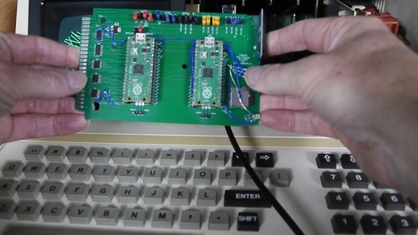
One of the PCB projects involved being held in the author's hands - a large-ish green board, with two Pi Picos visible on it

RP2040 And 5V Logic – Best Friends? This FX9000P Confirms!

Over the years, we’ve seen some modern microcontrollers turn out to be 5V-tolerant – now, RP2040 joins the crowd. Half a year ago, when we covered an ISA card based on a Pi Pico, [Eben Upton] left a comment saying that RP2040 is, technically, 5V tolerant for GPIO input purposes. The datasheets don’t state this because the reality of 5V tolerance isn’t the same as for natively 5V-tolerant chips – for instance, it doesn’t extend all the way to 5.5V for it to be ‘legally’ 5V-tolerant, as in, what 5V tolerance typically means when mentioned in a datasheet.

Having read that comment, [Andrew Menadue] has set out to test-drive the RP2040 GPIO capabilities, in a perfectly suited real-world scenario. He’s working with retro tech like Z80-era computers, using RP2040 boards for substituting entire RAM and ROM chips that have died in his FX9000P. Not only do the RP2040-driven replacements work wonders, using RP2040 boards also turns out to be way cheaper than sourcing replacements for chips long out of production!

Previously, [Andrew] used level shifter chips for interfacing the RP2040 with 5V systems, but he’s rebuilt a few designs of his without level shifters for the sake of this experiment. Now, he reports that, so far, those boards have been running long-term without problems. Together with [Eben]’s comment, this instills confidence in us when it comes to our RP2040 forays and 5V inputs.

There are a number of important caveats to this, that you should read up on. Some major points – certain GPIOs (like ADC ones) can’t take it, the GPIOs aren’t 5V-tolerant when set to output, and you shouldn’t feed the GPIOs 5V when the RP2040’s VDDIO is not powered up. [Andrew] points out one such case himself – one board of his has shed all level shifters except for the 8-bit address bus, which is driven by either the CPU or the RP2040 at different times, and that would result in 5V on an output-set GPIO when contention happens. All in all, if you’re working with 5V logic and your application is more hacking than business-critical stuff, you can shed the level shifters, too.

Continue reading “RP2040 And 5V Logic – Best Friends? This FX9000P Confirms!”

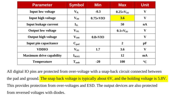
Section from the ESP8266 datasheet, showing maximum input voltage as 3.6V, but not mentioning ESD diodes to VCC and only talking about a snap-back circuit set to 6V.

Is ESP8266 5 V Tolerant? This Curve Tracer Says Yes!

Some people state that ESP8266 is tolerant of 5 V logic levels on its GPIOs, while others vehemently disagree, pointing at the datasheet-stated 3.6 V maximum. Datasheets aren’t source code for compiling the chip, however, and aren’t universally correct and complete either. [Avian] decided to dig deeper into the claims, conduct an experiment with an actual ESP8266 chip, then share the results for all of us.

For the experiment, he used a curve tracer – a device capable of producing a wide range of voltages and measuring the current being consumed, then plotting the voltage-to-current relationship. This helps characterize all sorts of variables, from diode breakdown voltages to transistor characteristics. The curve tracer he uses is a capable and professional-looking DIY build of his, and arguably, deserves a separate write-up!

The reasoning behind [Avian]’s experiment is simple – if the pin, set to an input, starts consuming a higher amount of current at a certain voltage threshold, then there’s gotta be some chip-internal structure, intended or unintended, that would be damaged at this voltage. Curve tracer in hand, he set up an ESP-01 module to set a GPIO to input, and started increasing the voltage.

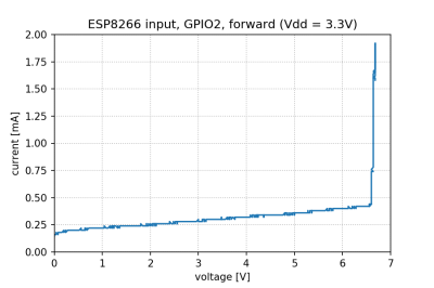
A curve tracer output graph, showing that there's no noticeable increase of current consumed across the range of 0V to 6.6V - current increasing from 0.2mA to 0.4mA in that range

The tests have shown that, while there’s a reverse biased ESD diode from GPIO pins to ground, there don’t seem to be diodes from the GPIO pin to the VCC rail – and those are the primary concern for 5 V tolerance. There does seem to be something functionally akin to a 6 V Zener diode internally, which should clamp the voltage before it gets too way high for the chip to handle. None of that should be a problem for 5 V compatibility, and it seems fair to interpret this as a confirmation of 5 V tolerance until someone shows otherwise.

[Avian] didn’t want to destroy an ESP8266, so the experiment was conducted with a 1 K series resistor between the curve tracer and the input – which might have biased the results a bit. On the other hand, adding series resistors in front of your inputs is an overall underappreciated practice, 5 V or otherwise. He also points out that, while the pins don’t seem to be adversely impacted by the higher input voltage, the bootloader might set some of them to 3.3 V outputs on boot-up, shorting your 5 V source to your 3.3 V rail — worth keeping in mind!

[Avian]’s research journeys are fun to follow, and we recommend you check his blog out; last time, we covered his research of an innocent-looking 3.5 mm jack hiding a devious audio compensation circuit. Since we first covered the ESP8266 in 2014, we’ve been researching all the things it’s really capable of, and we brought up the topic of GPIO 5 V compatibility way back in 2016 – it’s reassuring to finally put this question to rest!

We thank [Adrian] for sharing this with us!

Taking It To Another Level: Making 3.3V Speak With 5V

If your introduction to digital electronics came more years ago than you’d care to mention, the chances are you did so with 5V TTL logic. Above 2V but usually pretty close to 5V is a logic 1, below 0.8V is a logic 0. If you were a keen reader of electronic text books you might have read about different voltage levels tolerated by 4000 series CMOS gates, but the chances are even with them you’d have still used the familiar 5 volts.

This happy state of never encountering anything but 5V logic as a hobbyist has not persisted. In recent decades the demands of higher speed and lower power have given us successive families of lower voltage devices, and we will now commonly also encounter 3.3V or even sometimes lower voltage devices. When these different families need to coexist as for example when interfacing to the current crop of microcontroller boards, care has to be taken to avoid damage to your silicon. Some means of managing the transition between voltages is required, so we’re going to take a look at the world of level shifters, the circuits we use when interfacing these different voltage logic families.

Continue reading “Taking It To Another Level: Making 3.3V Speak With 5V”

Ask Hackaday: Is The ESP8266 5V Tolerant?

The ESP8266 is the reigning WiFi wonderchip, quickly securing its reputation as the go-to platform for an entire ecosystem of wireless devices. There’s nothing that beats the ESP8266 on a capability vs. price comparison, and this tiny chip is even finding its way into commercial products. It’s also a fantastic device for the hardware tinkerer, leading to thousands of homebrew projects revolving around this tiny magical device.

In every technical document, summary, and description of the ESP8266, the ESP8266 is said to be a 3.3V part. While we’re well into the age of 3.3V logic, there are still an incredible number of boards and hardware that still operate using 5V logic. Over on the Hackaday.io stack, [Radomir] is questioning this basic assumption. He’s wondering if the ESP8266 is 5V tolerant after all. If it is, great. We don’t need level converters, and interfacing the ESP to USB TTL serial adapters becomes much easier. Yes, you’ll still need to use a regulator if the rest of your project is running at 5V, but if the pins are 5V tolerant, interfacing the ESP8266 with a variety of hardware becomes very easy.

[Radomir]’s evidence for the possibility of 5V tolerant inputs comes from a slight difference in the official datasheet from Espressif, and the datasheet translated by the community before Espressif realized how many of these chips they were going to sell.

The best evidence of 5V tolerant pins might come from real-world experience — if you can drive a pin with 5V for months on end without it failing, there might be something to this claim. It’s not definitive, though; just because a device will work with 5V input pins for a few months doesn’t mean it won’t fail in the future. So far a few people have spoken up and presented ESPs directly connected to the 5V pin of an Arduino that still work after months of service. If this is evidence of 5V tolerant design or simply luck is another matter entirely.

While the official datasheet from Espressif lists a maximum VIH of 3.3V, maximum specs rarely are true maximums — you can always push a part harder without things flying apart at the seams. Unfortunately, unless we hear something from the engineers at Espressif, we won’t know if the ESP8266 was designed to be 5V tolerant, if it can handle 5V signals reliably, or if 5V signals are a really good way to kill a chip eventually.

Lucky for us — and this brings us to the entire point of an Ask Hackaday column — a few Espressif engineers read Hackaday. They’re welcome to pseudonymously chime in below along with the rest of the peanut gallery. Failing that, the ESP8266 has been decapped; are there any die inspection wizards who can back up a claim of 5V tolerance for the GPIO? We’d also be interested in hearing any ideas for stress testing pin tolerance.