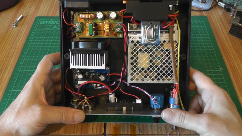
[Les] from [Les’ Lab] has designed a driver for laser diodes up to 10 watts, and decided to show us how it operates, tells us what we should keep in mind when designing such a driver, and talks about laser safety in general. This design is an adjustable current regulator based on the LM350A, able to provide up to 10 watts of power at about 2 volts – which is what his diode needs. Such obscure requirements aren’t easily fulfilled by commonly available PSUs, which is why a custom design was called for.
He tells us how he approached improving stability of the current regulation circuit, the PCB design requirements, and planning user interface for such a driver. However, that’s just part of the battle – regulating the current properly is important, but reducing the potential for accidental injuries even more so. Thus, he talks extensively about designing the driver circuit with safety in mind – using various kinds of interlocks, like a latching relay circuit to prevent it from powering up as soon as power is applied.
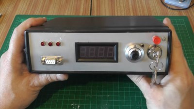 Of course, safety concerns go beyond the driver’s features, and so does [Les], feeling that we should know what goes into operating a laser of such power. He explains the importance of choosing proper safety glasses for the wavelengths involved – what the various relevant numbers mean, and how to use these numbers to choose glasses actually able to protect you from going blind on accident. Mounting everything in a solid way is called for, too – you wouldn’t want the laser to accidentally move away from the path you want it to shine in, since even reflections can be quite dangerous.
In the end, [Les] shows the driver in action coupled with a laser diode, and produces enough smoke that we are legally obligated to consider this a ‘smoke test’ – a successful one! He has big plans for that diode, and we can’t wait to see them come into fruition.
[Les]’s YouTube channel has videos about all kinds of electronics-related DIY builds, and is definitely worth going through if laser-adjacent topics are of interest to you. We’ve covered a few of his builds in the past, including a Raspberry Pi-based spectrometer and a high-voltage switch out of a simple spark gap.


Itʻs nice to hear from someone thatʻs seriously interested in laser safety. Iʻve worked with Class 4 lasers since the 70s and am pretty horrified whenever I see them sold as hobbyist toys.
@Greg Garriss said: “Iʻve worked with Class 4 lasers since the 70s and am pretty horrified whenever I see them sold as hobbyist toys.”
What about quack medicine:
https://quantum-healing-lasers.com/class-4-lasers/
Those actually works
Really? “Quantum Healing”? Pffft… I’m skeptical.
Thanks! Yes, exactly. Safety has come up a few times in the comments, and figured, why not.
Cheers!
Typical YouTube nonsense. The whole 16 minutes would fit on 1-2 web pages with links. Where is the READABLE schematic? I can’t read the P/N of the current-pass NMOS transistor from the video, even in full-screen mode. Is the NMOS transistor linear operation qualified (as it should be)? Why are you dropping such a high voltage to the laser’s low Vf? Use a much lower switching primary supply voltage (~3.3/5V?)followed by an analog LDO post regulator for the last volt or two. The LDO will give you massive noise rejection plus over-current protection and much higher efficiency. No big analog filter needed (BTW where is the schematic for that?), no big heatsink & fan needed.
Fair point, but some people prefer to see Video’s than view a web page.
The schematic appears readable on my current device (1024×768 crusty old laptop, perhaps check if YouTube is pushing you a 240p version or something.). I could upload it somewhere if you like? Suggestions welcome. The pass transistor is an IRF4905.
The supply voltage is already 5v, it was a requirement of my design, a single 5v supply. 3v3 is too low for decent compliance even with an LDO. As I remarked in the video, the heatsink I used is overkill. It was in the parts bin, so it was used.
Cheers!
Les
Nobody who is not just watching but wants to make prefer video over web page. And right, thanks for heads up on YT resolution; would never solve this myself. Now all is clear. You are Youtube star! Like, like, like, like, like! Aaaaah!
Nobody? That’s just not the case, there are absolutely people like this. Ever watched an interesting video about one of your favourite topics while exercising, for instance? Can recommend.
I’ll echo the other person and say that this is not true for everyone. The most obvious example is someone who wants to build something but doesn’t have a lot of fabrication experience or knowledge. There’s a lot you can learn from just watching someone experienced.
For instance, if you’ve never built a table out of wood before, would you learn faster from reading a book about it and all of the wood working techniques and tools you’ll need, or would you learn faster from watching a master carpenter build that table?
Neither.
From watching the video of the carpenter, you (might) see some things that no one thought to mention in the books. You won’t get the needed calculations from watching the carpenter build a table.
A good, properly written description with detailed drawings will teach you more about the design.
A well made video will show you how an experiences person goes about the actual tasks involved in the construction.
The big problem comes in that most videos on YouTube aren’t well made.
Making a good video is actually more work than making a written description with photos and drawings. For a good video, you have to plan what you are doing and how to film it to show the things you want to communicate. This involves a script (a written description) and possibly sketches to indicate things that the camera needs to capture.
That’s already the work involved in making a written blog post with photos.
Once you have your script, you have to record things to actually show the parts you want to communicate. This includes staging scenes and repeating scenes to capture things properly.
With all the recordings made, you get to edit it all down to the things you intended to communicate and then add a voice over and maybe text and pointers to indicate important things.
Despite all the work, you cannot put the same amount of detail in the description and voice over on the video as you can include in a written text.
A properly made video is much more work than a properly made written description with pictures and drawings.
Despite being more work, the video is of less practical use.
You cannot search it for a required bit of knowledge.
You have to watch it from end to end to be sure that what you need to know is there (or isn’t there.)
The knowledge density is lower for a video. It takes more time to transfer a smaller amount of information. In the same vein, it takes more data volume for the video. If you are looking up how to fix something by watching YouTube videos on your phone, you’ll use more data volume than reading how to do the same task.
————
I prefer books. I hated school. Videos are basically school – watch someone else natter on for an hour on a subject without touching the important bits you need to know and that you have to dig out of a book anyway.
Looking at the article on my phone, I read about the use of an LM350A in the article but saw on the schematic that it was an LM358 op amp. I build extremely low noise, stabilized, single mode diode lasers for holography. Switching power supplies make me nervous when powering up expensive, nanosec spike sensitive laser diodes…
@Les Wright said: “The schematic appears readable on my current device (1024×768 crusty old laptop, perhaps check if YouTube is pushing you a 240p version or something.)”
Hi Les. Yup you are right, that was it. I forced 1080p in YouTube and now everything is clear as a bell in full screen.
“The pass transistor is an IRF4905.”
The venerable IRF4905 uses a planar structure. I think it should be OK for continuous linear operation, but you might want to verify this with Infineon. Avoid MOSFETS that use tiled cells. With tiled cells in continuous linear operation one or more cells can turn on earlier than others and die due to thermal runaway.
“The supply voltage is already 5v, it was a requirement of my design, a single 5v supply. 3v3 is too low for decent compliance even with an LDO. As I remarked in the video, the heatsink I used is overkill. It was in the parts bin, so it was used.”
Now that the schematic is readable I see clearly that Vcc is +5 VDC. For some reason I picked-up ten volts, and seeing the big heatsink and fan reinforced my error. Assuming the laser has Vf = 2V, Vcc = 5V gives you a 3V drop-out. Surely you can find an LDO that can handle that. The LDO post regulator should cure the switcher noise allowing you to toss the linear filter plus it will dramatically reduce the heat dissipated in the pass transistor. In-fact if the LDO is adjustable it may be used to replace the pass PMOS transistor all together.
Simulate the PMOS. Infineon’s IRF4905 page has a Level-1 PMOS Spice model on it that will drop right in to LTspice. To use the model, in LTspice go to: Help > F.A.Q. > Third-Party Models. Also there are plenty of YouTube tutorials on using third-party models in LTspice:
https://www.youtube.com/results?search_query=LTspice+Third-Party+Models
This tutorial might be helpful with verifying the model, “MOSFET Characteristics using LTSpice”:
https://www.youtube.com/watch?v=ErpKbG7HCG0
The IRF4905 model is here:
https://www.infineon.com/cms/en/product/power/mosfet/p-channel/irf4905/#!simulation
Model direct download link:
https://www.infineon.com/dgdl/irf4905.spi?fileId=5546d462533600a4015356faeff336bb
Or here you go:
.SUBCKT irf4905 1 2 3
**************************************
* Model Generated by MODPEX *
*Copyright(c) Symmetry Design Systems*
* All Rights Reserved *
* UNPUBLISHED LICENSED SOFTWARE *
* Contains Proprietary Information *
* Which is The Property of *
* SYMMETRY OR ITS LICENSORS *
*Commercial Use or Resale Restricted *
* by Symmetry License Agreement *
**************************************
* Model generated on Jun 19, 96
* Model format: SPICE3
* Symmetry POWER MOS Model (Version 1.0)
* External Node Designations
* Node 1 -> Drain
* Node 2 -> Gate
* Node 3 -> Source
M1 9 7 8 8 MM L=100u W=100u
* Default values used in MM:
* The voltage-dependent capacitances are
* not included. Other default values are:
* RS=0 RD=0 LD=0 CBD=0 CBS=0 CGBO=0
.MODEL MM PMOS LEVEL=1 IS=1e-32
+VTO=-3.53713 LAMBDA=0.00549383 KP=23.3701
+CGSO=2.84439e-05 CGDO=1e-11
RS 8 3 0.0101265
D1 1 3 MD
.MODEL MD D IS=1.29014e-08 RS=0.00297795 N=1.46717 BV=55
+IBV=0.00025 EG=1.2 XTI=4 TT=0
+CJO=3.56968e-09 VJ=1.17553 M=0.500933 FC=0.5
RDS 3 1 2.2e+06
RD 9 1 0.0001
RG 2 7 6
D2 5 4 MD1
* Default values used in MD1:
* RS=0 EG=1.11 XTI=3.0 TT=0
* BV=infinite IBV=1mA
.MODEL MD1 D IS=1e-32 N=50
+CJO=4.83772e-09 VJ=0.625334 M=0.543532 FC=1e-08
D3 5 0 MD2
* Default values used in MD2:
* EG=1.11 XTI=3.0 TT=0 CJO=0
* BV=infinite IBV=1mA
.MODEL MD2 D IS=1e-10 N=0.4 RS=3e-06
RL 5 10 1
FI2 7 9 VFI2 -1
VFI2 4 0 0
EV16 10 0 9 7 1
CAP 11 10 6.08035e-09
FI1 7 9 VFI1 -1
VFI1 11 6 0
RCAP 6 10 1
D4 6 0 MD3
* Default values used in MD3:
* EG=1.11 XTI=3.0 TT=0 CJO=0
* RS=0 BV=infinite IBV=1mA
.MODEL MD3 D IS=1e-10 N=0.4
.ENDS
Not everybody wants to read – or create – a blog post, which is why YouTube is as popular as it is, and there’s great reasons why many hackers prefer videos added to their informational diet. I’d talk about those, but seriously considering these reasons would require some openness from your side, and it sure doesn’t seem like that’s what you came here with. As for the schematic being unreadable, I checked and that’s really a problem on your end, perhaps, a low resolution chosen somehow. That’s not to to blame you – if you used YouTube every now and then, you’d probably have known how to debug such a primitive issue, but hey, you seem to have your reasons.
Could be generational. I usually prefer a web page with a traditional schematic and a real BOM when talking about electronics projects. Not saying this is the case here but a huge percentage of YouTube videos contain a lot of blather. Really low signal-to-noise ratio. Gets way old. Talk talk talk nugget talk talk. And, it is impossible to search for something that was spoken if you are trying to find a piece of information that was said in the video.
On the other hand, there are several YouTubers that do some great stuff. The BlackTail studios guy (live edge epoxy tables) is great – high SNR.
The circuit itself is pretty much standard fare. Voltage reference, op-amp, transistor, FET. Nothing to see here. (No offense meant, BTW. It’s a simple circuit doing what it’s supposed to. There’s no need to make it more complicated.) I’ve built at least three versions of these for smaller lasers. (Nice vernier pot!)
What’s great about the video is Les’ descriptions of how he got where he got on it, which parts are safety relevant, and what they do. All the stuff that you need in addition to the circuit.
I didn’t see any safety circuits in the video. Just a basic current regulator with no safety what so ever.(over current
monitoring/interlock with redundancy etc)
Real men use laser valves.
40W K40 laser 180gbp
This project is less about power, and more about wavelength. I need 808nm to drive a tripled YAG laser I picked up. A CO2 laser is not suitable for that.