When looking at integrating a photovoltaic solar panel into a project, the naive assumption would be that you simply point the panel into the general direction of where the Sun is, and out comes gobs of clean DC power, ready to be used for charging a battery. To a certain extent this assumption is correct, but feeding a solar panel’s output into something like a regular old PWM buck or boost regulator is unlikely to get you anywhere close to the panel’s full specifications.
The keywords here are ‘maximum power point’ (MPP), which refers to the optimal point on the solar panel’s I-V curve. This is a property that’s important not only with photovoltaics, but also with wind turbines and other highly variable power sources. The tracking of this maximum power point is what is generally referred to as ‘MPPT‘, but within this one acronym many different algorithms are covered, each with its own advantages and disadvantages. In this article we’ll take a look at what these MPPT algorithms are, and when you would want to pick a particular one.
Powerful Curves
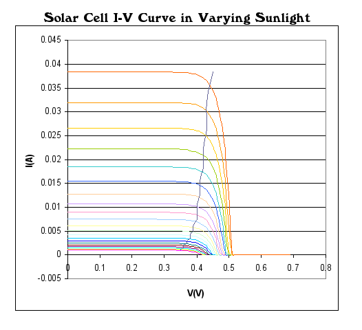
Solar cell specs usually quote an open-circuit voltage and a short-circuit current. Between these extremes, the voltage that a solar cell can produce depends on how much current it’s producing. As the current drawn increases, the voltage it can produce decreases.
Think of a nozzle at the end of a hose — the more flow of water you let out of it, the less pressure is produced at the exit. If you leave it wide open, you get maximum flow, but it spills on your feet. If you close the nozzle a bit, less water comes out, but it flies further.
Power is the product of voltage and current, P = I * V, and this is what we care about. In the specs, one of either I or V is zero, so no power is produced. Between these cases, there is a maximum power for the given illumination.
The goal of a power-point tracker is to resist the flow of current out of the solar cell so that it’s operating at an intermediate current and voltage that maximizes its output: opening the valve so that the water pushes a water wheel as fast as possible.
It is this simplicity that also hides the complexity of MPPT: in the case of a PV solar panel, its MPP will continually change as solar irradiation changes due to passing clouds, the changing angle of the Sun, and many other factors. This means that the MPP has to be continuously updated, which means determining the optimal voltage with minimal under- or overshoot. Over the years, a number of different approaches to solve this problem have been developed.
While some variations and custom MPPT algorithms exist, the following are the most popular algorithms.
Constant Voltage
One of the earliest and most basic MPPT algorithms, Constant Voltage (CV) tracking, changes the output current to maintain a constant reference voltage. This approach uses a set fraction of the open circuit voltage, usually around 80%, which means that technically it does not track the MPP at all.
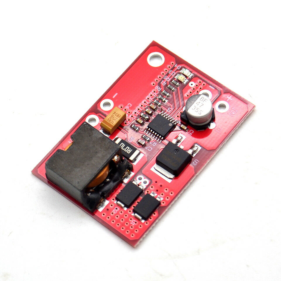
It is still a useful approach because of its simplicity, but it offers low efficiency and suffers in situations where the solar panel is poorly situated and doesn’t see full sun. The low requirements makes it an ideal target for low-cost single-chip solutions, such as the ubiquitous MPPT ICs from Consonance-Elec, such as the CN3722 and CN3791.
A basic 5 A CV MPPT board can be obtained in a variety of generic guises for often less than $10. This makes them ideal for hobby and cost-sensitive applications where efficiency isn’t paramount, and a loosely approximated MPP is sufficient.
Perturb And Observe
This MPPT algorithm is a fairly straight-forward true tracking algorithm. As the name suggests this algorithm is based around the slight nudging of the MPP current set point, measuring current and voltage, determining whether the power produced increased or decreased, and repeating the nudge accordingly.
While quite efficient even in this basic form, the main issue with the perturb and observe algorithm is that it tends to oscillate around the MPP, which will reduce the overall efficiency.
In order for this algorithm to determine whether it needs to adjust the MPP set point, it has to change this set point so that it can observe the effect of this change in the form of the output power. Although this will track the optimal MPP, it will constantly oscillate around it. Here making the adjustment step size as small as possible may seem like a reasonable optimization, but this leads to the system responding very slowly when a rapid change occurs, such as a cloud obscuring the PV panel.
This approach is a good intermediate solution between the simplistic constant voltage approach and something yet fancier.
Incremental Conductance
Incremental conductance measures the changes in current and voltage to predict the effect of a voltage change using the system’s conductance (ΔI / ΔV) — the slope of the power curve. Where perturb and observe takes fixed-size steps and tests if they’re in the right direction, incremental conductance modifies the step size depending on how far away from optimal it is. This has the effect that when it’s already at the MPP, the step size goes to zero and it simply sits there.
Calculating the slope — the ratio of changes in voltage and current — is more sensitive to error than measuring the levels themselves. So while incremental conductance uses a better optimization strategy, it also comes with the most severe hardware requirements, including precision components and a controller that can constantly perform the required calculations. This makes it a good choice for an application where efficiency is paramount, and the available budget generous enough to accommodate the extra expense.
Only The Beginning
The preceding is only a minimal primer on MPPT and the three most common algorithms, and the devil is in the details. For instance, in both the optimization methods, what happens if a bird passes over just as you’ve perturbed the setpoint or taken a voltage step? You might erroneously conclude that the change you made caused the decrease in power. Temperature and other real-world conditions also play a part, so what works on paper may not in practice — helping to explain the persistance of the constant voltage method.
But none of this is so complicated that you shouldn’t implement your own MPPT controller. One such example is found for the STM32F334 microcontroller in Application Note 5324 (AN5324), which details the software and circuitry required to use the high-resolution timer and other peripherals like the ADC and embedded opamp in this MCU to implement what is essentially a perturb-and-observe algorithm that controls an LLC switching mode converter.
While an off-the-shelf MPPT controller is probably the best choice for any project where things should Just Work™, they also form one of those intriguing devices that are simultaneously very simple and as complicated as you want them to be, making them for an excellent hobby project idea.


Here’s one built around an ATTiny44:
http://www.zabex.de/site/mpptracker.html
Interesting article, thanks! A quick google reveals more algorithms:
Fractional open-circuit voltage: This algorithm is based on the principle that the maximum power point voltage is always a constant fraction of the open circuit voltage. The open circuit voltage of the cells in the photovoltaic array is measured and used as in input to the controller.
Ripple Correlation: If the grid current is in phase with the grid voltage , the instantaneous value of power injected into the grid [] used to determine converted power, and you vary the current (somehow) to maximise that. (I suppose that factors in the inverter efficiency too).
Current sweep: The current sweep method uses a sweep waveform for the array current such that the I-V characteristic of the PV array is obtained and updated at fixed time intervals. MPP voltage can then be computed from the characteristic curve at the same intervals
Temperature method: This method estimates the MPP voltage ({\displaystyle V_{mpp}}{\displaystyle V_{mpp}}) by measuring the temperature of the solar module and comparing it against a reference.[25] Since changes in irradiation levels have a negligible effect on the MPP voltage, its influences may be ignored – the voltage is assumed to vary linearly with temperature.
What you might also usefully point out is that the power curve usually has a single maximum, which makes life much easier.
[abjq] I found the POST stuff,
Could you leave a contact on SLAG for me?
Or maybe [Elliott Williams] could be an intermediary?
Ah! Memory swapped into position, I had to shuffle something out of the way to make sense of that. :^)
I have a few projects on hackaday.io you could go through that maybe?
Oh! Yeah! Much better.
“What you might also usefully point out is that the power curve usually has a single maximum,”
*If* you have a single panel or your panels tend to have common illumination over the day. Partial shading events (clouds) generate multiple peaks, which is why it’s important to get the timescales right. In addition, if for some reason your panels don’t all have the same orientation, you’ll obviously end up with multiple peaks if you’ve only got a single MPPT. This might sound dumb (use more than one!) but depending on the orientation it might not be necessary (if the panels are basically complementary – one or the other is illuminated, not both): you just need an MPPT that’s not stupid enough to get caught in a secondary maximum.
Sorry, I should have said:
What you might also usefully point out is that the power curve usually has a single _instantaneous_ maximum.
The power of ambiguity! I wonder if I could instead harness that…
Again – if you have a single panel. With multiple panels connected together, each of the panels has their own maximum, and if the illumination conditions of the two are different… you have two peaks in the same power curve. At the exact same moment. Google MPPT partial shading and you’ll see a bunch of work on this.
I’ve actually had direct work on this due to a balloon experiment I worked on with an omnidirectional PV array: the MPPT was quite old (and dumb) and actually did get stuck on a secondary maximum, trying to maximize the power from the panels that were only getting indirectly illuminated. Looked like it would be a big problem, but thankfully it did a full scan often enough that it got out of it quick enough to not be a fatal issue.
Well with domestic setups we usually connect multiple panels in series, and two panels have the same current, as a constraint of series working.
My gut feeling here is that the string acts as a single panel, as partial shading operates on (say) on a few cells in the panel (all connected in series anyway) there would still be one instantaneous maximum for the string. However, non-linear effects can easily invalidate the “gut feel” model, so I suppose I’ll have to try it out.
One of my roofs has very sharp differential shading at different times of day, and on that one I operate a microinverter per panel, and then the mains outputs are paralleled up, which makes the best of a bad situation (this roof has other benefits though, ease of access for cleaning being one.) Each panel then does operate MPPT individually. For an omni array, mutliple smaller trackers would make more sense.
For an example of the math you can see https://doi.org/10.1186/s41601-018-0111-3 or https://arxiv.org/pdf/1810.12431 , which also includes data.
Also:
“and two panels have the same current, as a constraint of series working.”
While this is true, series-connected panels typically have bypass diodes in them to prevent hot-spot heating: if you try to shove current through an un-illuminated panel, you’ll reverse-bias it and it’ll be *consuming* power and heating up, and… well, that’s very bad.
The bypass diodes generate multiple peaks in the power, because you effectively can choose between “bright panel high voltage, low current relative to max + dim panel low voltage current at max” (so high overall voltage) or “bright panel low voltage, max current + bypass diodes on the other panels” (so low overall voltage).
Depending on how bad the mismatch is, you can easily have very prominent peaks in the overall IV curve. And then obviously with parallel strings it’s easy to have multiple peaks since the overall IV curves just add.
Again, see the above links, or google app note PVA-600-1 from Solmetric, which explains things pretty well.
Thanks, I took a look at the papers.
It must be said that the ones that show significantly-varying multiple peaks (where a local maximum is quite a bit lower than the true maximum) are all in parallel string configurations.
This is why it’s not a great idea to use parallel strings, much better to feed each string into a separate input in the inverter that can track the MPP of that string independently.
Where the string panels are ALL in series, the worst graph I saw showed a lower peak no more than 5-10% off the main peak, so no great shakes.
So I’ll leave it as: “What you might also usefully point out is that the power curve for series configurations usually has a single _instantaneous_ maximum. If you insist on using parallel cells or panels, you are on your own!”
It just depends. Parallel strings obviously generate significantly worse IV curves for an MPPT to handle because they just add, and most series configurations aren’t *bad* because there aren’t usually *that* many of them anyway.
Of course the major point is that in residential situations you’re not going to really notice weird edge cases where it gets stuck for like 15-30 minutes or something. It’s a much, much bigger deal where you’re running directly off solar power and your battery reserve is only like 30 minutes because you’re in a situation where you have constant sun.
Yes I could see that would be a problem north of the Arctic circle…
Nice nod to Horowitz and Hill.
Has anyone tried sensing the illuminance with a photodiode / LDR and storing the MPPT for each value in non-volatile memory?
Yes. And this is done via an so called “irradiation sensor”.
I thought so; I’m still curious about storing a panel’s V-mppt vs irradiance curve (which should be constant at a given temperature) instead of twiddling the voltage periodically.
Was wondering this myself! There’s all sorts of complications, like when a cloud covers half of the cell but not the photodiode, or termperature-shift effects.
But I can’t think of why not, except maybe complexity/parts count. And that’s not the sort of thing that would stop a prototype.
I was wondering about what to do with the generated electricity.
One idea is to sense what power is being exported (which I won’t get paid for) and then use it in an immersion heater in another part of the house.
An solar sensor here would help with interlocks so my new project doesn’t make an expensive mistake and suck power down from the grid when export power is impossible, or unlikely. Also time of day will help…
If a cloud’s shadow covers only half the cell it’s a pretty sharp cloud, or a low flying blimp. As for complexity, a few extra analog components looks like a small price to pay for Moar Powah (per panel).
The irradiation sensor may not be in the exact same location as the panel, especially if you have a whole field of them.
Also, substitute the cloud with a shadow from a tree, or a fallen leaf.
Am I right to assume that PWM has an efficiency around 70% and the different MPPT methods 94% – 99%?
Just to put it into perspective.
All other things being equal, yeah, those numbers are correct(for the solar regulator itself). But they (usually) are not all that equal, and the total system efficiency of a PWM can be much worse than that. If you’re not working close to the margins, a rule of thumb is quite handy and saves a lot of details…
Many (most?) PWMs are just chopping the raw panel output voltage. Since a capacitor big enough to actually smooth that out is usually bulky, expensive, and temperature-sensitive, they expect the load itself to act as the smoother. For a solar battery system, it can work well enough as long as the panel voltage at this effective load doesn’t rise too high for this particular battery chemistry. But long before it causes direct harm to the battery, you’ll see a decrease in efficiency. More of the energy will go into heating the electrolyte and less will be stored in the chemistry. Technically, several modes of battery damage are related to simply overheating the electrolyte. Even when you don’t care for your batteries, this heat represents energy that was not successfully stored…
Also, a simple raw-panel-voltage PWM cannot force any charge into a battery whenever the panel voltage lower, (or insufficiently higher) than the terminal voltage on the battery. At the same time, it will not down-regulate the instantaneous panel voltage when it’s above the safe charging voltage. Thus, you’re forced to either pick a safely low voltage for your array and lose all power produced during periods of moderate irradiance, or pick an efficiently high voltage for your arrray and risk cooking your batteries on a hot, clear day, when the batteries are already fully charged. (Admittedly, this is more of a problem for lead-acid systems, as the cost and maximum achievable lifespan doesn’t usually justify installing a BMS with cell-balancing and protective cutoff voltages).
Many (but not all) MPPTs are designed as MPPT-controlled variable switching regulators. You do have to be careful though, because there are some airquotes MPPT airquotes designs that purport to maximize the IV curve via simple PWM. Most of the time, it’s marketing woo, but a few of them legitimately do what they say (if usually only in a narrower set of conditions than was advertised).
Full switching-regulator MPPTs can achieve nearly 99% efficiency. But this requires really stringent choices of critical components. Achieving the last 10% of the efficiency is more than 90% of the cost, especially for nontrivial wattages. Also, as is true of most switching designs, they achieve rated efficiency only near their maximum design load. This is because they all have some specific minimum constant overhead, and it’s only when they’re operating near full rated power that this constant overhead becomes negligible.
If you ever have to design a system that simultaneously maximizes battery time-to-failure, maximizes watt-hours-usable-per-day, minimizes total panel area, and has to sanely handle or recover from all anomalies without human intervention, prepare to discard ALL rules of thumb (and double check every bleeping formula and table… ALL spec sheets lie, some are just consistent in their lies :)
There was an article on here (last year?) about using nickel-iron batteries configured to be overcharged more often than would seem like a good idea. The idea was to overcharge the batteries such that they electrolysed hydrogen for capture and reuse or sale. The only downside seemed to be that the cells needed water to be added more frequently.
Kudos to Joe Kim for the graphic in the Title!
You mean with the nod to Horowitz and Hill?
Oh, I missed the reference (obviously).
Time to pull the old AoE off the shelf.
I took a class about solar energy and dc/dc systems in college, did the final project on implementing and analyzing different mppt algorithms in matlab fed with real data gathered from our uni’s panels in the clean energy center under different weather conditions. It was actually a pretty fun project.
What won? Can’t leave us hanging like that!
(not sjm4306, but…) I did aconstruction manual for small solar cells as student research project, which kind of used dV/dt, and my prototype worked fine for the last 10 years. Which algorithm wins always depends on the surroundings it has to deal with, since every algorithm finds the MPP under lab conditions. For example, if you have to deal with emerging shadows, an algorithm which regularly sweeps the whole range wins, otherwise a non-sweeping algorithm is probably better. Anyways, sjm4306 will be able to give more and better researched details than me.
I’d have to dig up the thumb drive the report was stored on, it was a good 10 years or so ago so my memory is pretty fuzzy on the details unfortunately.
Oh please do, that’s interesting!
I’ve used an MPPT controller which uses a feedback network to servo the input current from the solar panel. The implementation notes included examples of how to add an PTC resistor to vary the set point according to panel temperature (which shifts the entire output curve), and it would not be very complicated to also monitor the return current to shift the setpoint forward and backward to make the rising slope.
However, the simple fixed voltage setpoint plus temperature compensation gets you about 95% there and the rest is just about optimizing for very low light levels which won’t really matter anyhow.
I have been wondering how low can you go, and will measure moonlight, starlight etc… I expect there is something lurking. I also wondered if it’s low, how much random noise you might get…
PV-cells have pretty much leakage current due to the large area covered, and when the generated current drops below that, the voltage will collapse. So no energy output under moonlight conditions, unless you manage to get rid of the leakage current.
Pretty much. A 2 Watt panel in regular room lighting is barely enough to show a voltage in a common multimeter.
One of the things I did was measuring the current output into a constant voltage from an adjustable PSU. You can quickly dial in a rough shape of the I-V curve – and it’s usually not “neat” like that in the example – the slopes go all over the place due to various reasons so the definition of a “maximum power point” can be somewhat vague. It is there, but you may have better results aiming well below the MPP to get more consistent power output.
Not gonna lie, but the first thing that came into my mind when I read the head line was “wait, Hackaday is doing something with Power Point?”
Clearly, I picked the wrong week to stop sniffing glue. :)
You mean MS Pointless Power?
Tangibly related, but I really wonder if (and how!) things like SMA’s “Shadefix” work. They claim to eliminate the influence of shade by the means of superfluous marketing words.
That’s an optimizer, but it differs from most optimizer systems in that only the shaded panels need optimizers, greatly reducing the cost.
Any idea how an 80% Constant Voltage (CV) PPT is different than a buck converter connected to the panel?
The buck converter regulates output voltage, so in the same moment the load is bigger than the solar power, the regulator pulls down the cell voltage to the output voltage, and the delivered current drops to the current the cell can deliver at that voltage.
For MPP-Tracking you have to regulate the input voltage or current. Since these are coupled by the I/V-curve you need one variable to control them, and a second, independent variable to control the output I/V (coupled by the curve of the connected load). But the only controllable variable on the buck is the duty cycle, thus you cannot regulate the output voltage and track the MPP at the same time (but you can switch between MPP-tracking and voltage regulation when reaching the desired output voltage)
Been pondering various ways to implement MPPT for a while, mostly for fun.
One “simple” solution I have figured is:
On start up, sweep the load current up and monitor the input voltage. Calculate input power at every point and buffer the last few points. (so we can return to them later.)
When the power starts to drop as we pass the MPPT point by some margin (as to account for noise), we stop increasing the load current and jump back to the “optimal” point we found earlier. (The optimal point can be assumed by looking over a few points on our sampled I/V curve as to remove some influence of noise. Effectively averaging the line over only the more optimal points.)
If the amount of light hitting the panels changes, then this will make the input voltage to our constant current load change.
When the input voltage moves away more than a set distance from our “optimal” I/V point we found. Then we know our “optimal” point isn’t all that optimal any more since conditions have changed. And therefor need to find the new one by sweeping in the desired direction. (if V increased, then our current also needs to increase by some yet unknown amount, and vice versa if V decreases.)
By sweeping and logging the points we can calculate power output over each point, sweep past the MPP by a bit as to see the curve drop on the other side, average and jump to the “best” point again and wait until things changes once more for another sweep.
In regards to shading and such happening during the sweep and “skewing” the results. Here the question rather is how fast we can make this control loop to ensure such events are slow in comparison so that our sweep largely happens in a “static” environment. (parasitic capacitance will be our enemy here.)
In regards to “losing power by sweeping past MPP”. We don’t need to sweep that far past, only enough to see that the curve slops down again. So we will still be more or less close enough to not lose any meaningful amounts of power. Same story applies to when we notice we are “outside of MPP” and initiate a new search, we would still be very close. So worst case maybe we loose a fraction of a percent unless ambient electrical noise limits our measurement resolution sufficiently.
However, there is likely better MPPT solutions used in the field.
I’ve implemented a couple of MPP circuits for a couple of solar powered model airplanes I built. The first used an individual solar cell to constantly measure the open cell voltage and then adjusted the load the array fed until the load voltage dropped to a set value. This worked pretty well and was simple to implement and rapidly accounted for clouds. But It did not account for thermal changes. As it turns out, cells with no load warm up more than cells that you’re drawing power from. In an airplane, there is also additional cooling from air flow which all result in higher cell voltage. The best solution for me was to open circuit the array, grab (RC circuit) the open cell voltage and then drive the load to a fraction of it which was about .5v per cell. I used 555 timers to to module motor speed(and hence load) which resulted in a 6 hour flight with no battery involved . Incidentally, any of these mpp methods can lead to system oscillations if the changing output is not buffered adequately with a battery or use of an autopilot. Eventually I used this arrangement to set FAI model airplane world records for distance and altitude using no battery both of which have been surpassed.
That sounds really cool. Do you have a link to the details?
How about an article on DIY single and dual axis solar tracking for photovoltaic systems?
The usual way to get the best average annual sun exposure is to mount the array facing due south (or north for southern hemisphere) and angled to exactly match your latitude.
Around the equinoxes it gets the best sun angles. Around the summer solstice the sun angle is off higher, which is less efficient but somewhat compensated due to less atmosphere distance the light must penetrate.
Around the winter solstice is the worst. The low sun angles reduce insolation both from being off perpendicular and from the greater atmosphere distance to penetrate. There can also be more cloud cover, more rain, and snow blocking light or covering the panels.
Tilting vertically (altitude) to always face the panels perpendicular to the sun’s height above the horizon maximizes the insolation throughout the day. It’s fairly simple to build one or a few quite large, one piece arrays to tilt vertically. Many people build theirs with a manual adjustment which they change periodically, weekly, monthly, or seasonally – depending on how much they want to improve efficiency.
Tilting horizontally (azimuth) adds a bit more power production but tilting a large array can require a very massive mounting, and raising it up higher can be required for the lower corners to clear the ground in the morning and evening. It’s more practical to 2-axis mount multiple small arrays, but that takes up a lot more space so the panels won’t shade each other before and after solar noon.
I’d want to build one large array with only automatic altitude tracking. I’d make the tracking system completely independent with its own PV panel just large enough to run the tracking system and power the actuators. It would have a manual override, angle adjustment, and disconnect so that the array’s angle can be adjusted for maintenance, then disconnected and locked out so it will stay put.
There have been several covered. Just need to search for it.
Here’s one I’m looking at trying:
https://youtu.be/wL9PcGu_xrA
Another approach is to look at your usual daily usage. In my household’s case, breakfast time, and afternoon are peaks.
Then point each set of panels perpendicular(ish) to the sun to cover each use case.
If your panels are not perpendicular to the sun at midday – so what – if you don’t use the power at that time?
Once you are within 30 degrees of the sun, you get 70% theoretical maximum, so that covers off quite a few hours either side. I suppose you might crank the panels by hand to cover off winter and summer solstices, 4 times a year would be enough.
If the panels aren’t getting 100% full incident sunlight, they degrade slower so it isn’t all lose-lose (probably why in the UK quite old panels are still ~80% or original output because they spend a lot of the time under cloud….)
>so what – if you don’t use the power at that time?
In the large scale, solar panels are installed not to generate power, but to generate subsidies: to sell the power at guaranteed prices and/or net metering to offset your power bill. For most folks, using their own solar power is not practical and the investment is not worth the money.
With respect, I disagree. Perhaps you are referring to home solar exclusively, however there are all manner of vehicles vessels and temporary dwellings for which solar is a great option, and economical if done well. Full disclosure: I did a conversion on my van. No affiliation here, and I haven’t used any other system, but I really like my Trimetric monitor and charger from Bogart Engineering. Bare bones interface but intelligently designed and inexpensive. It takes the output from 300W of panels on the roof and charges two 6V golf cart batteries. It also has a continuous serial data output which I was able to read with an arduino and save to SD card. Lights, chargers for phones and laptop, a vent fan, and a fridge, which has been running continuously since I switched it on seven years ago. Maintenance? I have checked the water in the batteries about 6 times, and filled them twice. That’s it. I was going to tie it in to the alternator but didn’t get around to it and now see no need. I did have to jump myself once when I left the keys in the ignition…
Best advice I got was no need for best/fanciest. No lithium Power Brick Wall Slab, no AGM or gel. Golf cart batteries are cheap, and designed to have the crap kicked out of them whilst smiling. Don’t spend more than a dollar a watt on your panels, and match your storage to your panels. Too much panel and you’re charged by 10 am, too much storage and you take too long to recover from big draws. The latter is worse, those batteries like to be topped at least every couple days and shouldn’t be drawn down too far past 50 percent. Start with an energy budget and add 30 percent comfort zone then size your system to match. Don’t skimp on cable sizes or safety equipment, a loose cable tied right to positive with no fuse becomes a welding electrode with its own agenda. Best of all is I don’t own a loud stinky genny. All in all it has been super rewarding.
Wells
That largely depends on where in the world one is. Different countries have different subsidies and different power prices.
If one gets paid more for the selling solar power than it costs to buy power from the grid, then one lives in an area that is currently pushing hard for solar installations, but that is often just temporary.
But at least where I live the cost of using one’s own solar power is a lot cheaper than buying power from the grid. And selling power to the grid only gives money for the power. The grid has transfer fees paid by the load. And transfer fees at least here in Sweden is often more expensive than the power itself. (depends on everyone’s collective strain on the grid and where one is.)
However, there is a subsidy for covering some of the cost of construction for a solar installation, and there is also a tax reduction for every kWh sold up to a cap of 18k sek (30 MWh per year.) So when one buys power back from the grid one don’t have to pay as much tax on it, but there is still the transfer fees, so buying is still more expensive than using one’s own.
In short, the installation pays for itself through not having to spend as much on buying power. It is a market, so sell 1 kWh and get less than that in return later for the same monetary value.
It is like buying and selling anything else. There is transaction, handling, transport, and other fees associated on top of the value exchanged in the product itself. Not to mention taxes. And this is true in most countries, except those with excessive subsidies.
Then there is Germany where to my knowledge one has to pay energy tax per kWh for one’s own solar installation if the installation(s) produces more than 10 kW. (someone can correct me if I am wrong, might have just been a law proposal.)
>but that is often just temporary.
So will be the solar panels. The main issue is that solar power comes in at times when the homeowners are not consuming it, so installing panels to actually use the power becomes uneconomical beyond couple hundred watts that you can guarantee to use (ventilation etc.)
As a result, IF you have many kilowatts of solar on your roof, you’re probably getting subsidized. Vice versa, if you aren’t getting subsidies, no solar.
> Germany where to my knowledge one has to pay energy tax per kWh for one’s own solar installation
For commercial and industrial premises.
For a smaller city home, my power company actually reports my actual daytime idle power consumption at just 150 Watts when I’m not at home. I would expect a larger detached home in the suburbs to consume 2-3x that, but still not many kilowatts.
Hence my interest in what to do with the power that I cannot otherwise use.
Obviously, one approach is to start using it more in the daytime when the sun is out (e.g. washing machines).
My parents had a water heater then dumped off the excess power. This cuts down on fossil fuel usage – a good thing right? You can dump 4-5kW into an immersion heater.
With many of us working from home at least part time now, another idea is a smallish battery + inverter, to cover off maybe 1kWh, but that can output 3kW. This covers “making a cup of tea” and similar peaks from short thirsty devices. Also it can dump its output at night. It must be smart enough to only charge when solar is generating excess.
Secondhand panels and MPPT inverters were quite cheap 6 months ago,in the UK, but I have noticed, even secondhand prices are going up, for some strange reason…
I spent some time characterising 12v panels and benchmarking solar regulators and found that performance is similar when panels were matched to a battery of similar voltage (12V panel might have open circuit voltage of 22V). In the middle of the day under enough sun, performance between architectures was similar. In the morning and evening the mppt would perform better only there wasn’t as much energy available from the sun at this time anyway.
Also the second point is that there are two modes of operation. When there is more power available from the panel than the electronics are using, or when there is less (i.e. battery is charging). Depends on the overall design of the system how long the solar regulator will spend in each mode. The more time spent in the former then mppt isnt as useful. More time spent at the mpp you probably risk over time battery going flat.
Couldn’t the position of the sun be computed using astronomical math ?
The choice of MPPT very much depends on the application. As others have stated household power with multiple panels/strings with shading benefits from the optimisation provided by complex multi channel mppt,
Remote water pumping is another application that greatly benrfits from MPPT as the optimum load voltage (pump speed) varies with the available power (as well as the optimal panel voltage)
but some systems benefit overall with no MPPT at all. remote power battery charge is a good example . a well matched PWM ( direst switched connection with no voltage conversion) is often the best solution. the efficiency gain from mppt in these cases is very small but you pay for that with decreased reliability (because the energy storage elements required for MPPT ( electrolytic capacitors) have a finite life , especially in harsh high temperature environments). By Well matched PWM i mean a PV panel whose operating MPP is close to the Load voltage. for example a legacy 36 cell pv panel has a MPP of 17-18v which drops to about 15v under operational temperature conditions . if we allow 1v drop in cabling and controller then we are down to 14v which is pretty close to the charging voltage of a lead acid battery. so in this situation there is very little to be gained by mppt. modern cells have a greater “Fill Factor” which essentially means their mpp is at a slightly higher voltage so 32 cell panels are now often used for direct 12v battery charging. less cells means, for given panel size, each cell can be larger which gives a greater charging current.
its also worth noting that the top of the mpp curve is not symmetrical. the cost of operating 5% under MPP voltage is less than the cost of operating 5% over the MPP voltage so when choosing a very simple MPPT algorithm, like CV, then it pays to set it a little lower that the optimum