The exact airfoil shape of a wing has a massive effect on the performance and efficiency of an aircraft and will be selected based on the intended flight envelope. If you’re moving beyond foam board wings, 3D printing is an excellent way to create an accurate airfoil, and [Tom Stanton] provides us with an excellent guide to modeling wing sections for easy printing.
[Tom] used the process demonstrated in the video after the break to create the wing for his latest VTOL RC aircraft. It was printed with lightweight PLA, which can ooze badly when it stops extruding. To get around this, he designed the wings and their internal ribs to be printed in one continuously extruded line.
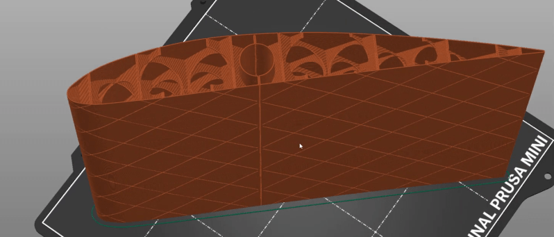
He wanted a wing that would allow a smooth transition from hover to forward flight, and used the Airfoil Tools website to find and download the appropriate airfoil profile. After importing the profile into Fusion 360, he created internal ribs in a diagonal grid pattern, with lightening holes running along the length of the wing. A cylinder runs along the core of the wing to fit a carbon fiber wing spar. The ribs are first treated as a separate body in CAD and split into four quadrants. When these quadrants combine with the outer shell, it allows the slicer to treat the entire print as a continuous external perimeter line using “vase mode“.
These steps might seem simple, but it took about 3 weeks of experimentation to find a process that works. It’s primarily intended for straight wings with a continuous profile, but it should be adaptable to tapered/swept wings too. A well-designed airframe is essential when pushing aircraft to the edge of efficiency, like solar-powered plane to fly overnight.


Very cool for 3d printing of anything that has to be a light, load-bearing structure. Taking to the next step, define the shape, define the loads – tension, compression and shear, then define the infill that optimizes weight.
That’s topological FEA. I can see someone writing a plugin for that for a slicer, but FEA is a deep field before you even consider topological optimization, and very computation and memory intensive. I’m not saying it won’t ever be implemented for a slicer, but it would be a really big lift.
I don’t think it’s necessary to have the slicer do the FEA. That is the job of the design program you are using.
There is significant sophistication in slicers already for infills. There might be infills superior to the one being used here. If not it should be possible to design that infill method into the slicer. That way you don’t have to spend time modelling it.
Examples of what is currently possible with PrusaSlicer:
https://blog.prusa3d.com/everything-you-need-to-know-about-infills_43579/
There are adaptive infills already implemented, which are designed to save weight while retaining strength. They do this by spacing out infill differently as it approaches the load balancing surface.
So while it’s certainly not trivial by any stretch of the imagination, I expect it is possible for your design software to perform the FEA and then pass that information along to the slicer. Informing it that this area needs “80%” strength, while this other area only needs “30%” and allowing the slicer to use it’s knowledge of the plastic being used to infill the areas appropriately.
couldn’t you just print at 5% fill rate with correct fill pattern (or maybe even less)?
You don’t get the vasemode spiral print in that method (which is important for this filament), the infill ribs would be solid when they don’t need to be and the important internal structures would still need to be manually laid out. So when you need to do some manual layout anyway you might as well go further and plot the whole thing out.
Weak axis is down the length of the wing?
Wing section length limited to Z range of printer?
What is the weight savings vs foam and film covered balsa?
I’m not sure this makes sense. Gonna be a bitch to repair.
I’d just do the hot tensioned wire foam wing thing, I’m lazy and know that works.
Also: There has to be a way to stop the ribs from generating turbulence via associated surface cracks. Bottom of airfoils particularly should be as smooth as glass. Turbulators on top should be just in front of the natural flow separation point at max design AoA (use Xfoil), not on leading edge.
I had the same thought, just hot-wire foam between the required airfoil templates in the way it has traditionally been done by aeromodellers for decades. It would have been a lot less effort.
To be fair, it’s hard to improve on things that have been hacked on as long as model airplane wings.
Worth a try. But knowing when to quit is also important.
Are you serious? Less effort for who? Thousands of people can now download this model and print it easily using off the shelf components and a standard 3D printer, and it’s only going to get easier as the technique gets refined. This level of reuse and amateur engagement just isn’t possible with manual methods
That places limitations on the possible airfoil profiles you can create. e.g. you could never create an airfoil that exhibits proverse yaw (negative pitch at wingtips, bell spanload rather than elliptical) using the tracing method, without needing to piecewise chop the wing into multiple segments and then bond them together. A 3D printed form lets you produce arbitrary variations of airfoil profile along the length without constrains of linearity between ends. You can also embed mounting points for internal components (e.g. servos and pivots) into the wing structure directly.
If you wanted the best of both worlds, you could produce two 3D prints: one with the internal spaceframe structure, and one as a buck for the wing skin (e.g. CF layup). Mould your skin, then slide the internal structure in and bond. That way you get a lighter and stringer structure than foam core, whilst having a lighter and stronger skin then can be 3D printed.
Wings are always going to a bitch to repair if you break them, this method to me seems like the easiest though, as its just let the printer do its thing and exchange the broken part for the new…
I suspect this is very very much lighter and stiffer. Certainly has been in every comparison of similar wings with the different construction methods I’ve seen, and it makes sense – its foamed PLA a pretty stiff material laid down about as minimally thick as its possible to conceive of while also being a foam for that extra little bit of weight reduction, with solidly shaped internal geometry and the main spar going full length so the ribs and wing need very very little strength really – only handling their own area’s wing loading enough to pass it to the spar. Compared to a traditional hotwire foam cut where the foams used tend to be a bit more flexible and weak so just can’t be cut as thin as the PLA can be extruded, and are probably of similar density – so just on the thickness its going to be a fair bit heavier.
Film covered anything could potentially be lighter and ‘better’ if the wing you are trying to create suits the method well, but getting that super sleek smooth surface finish just doesn’t ever happen, the ribs always seem to tell at least a bit. It is also heaps and heaps of manual work in assembly and more design of the internal wing structures to get the finished profile you want with the required stiffness…
The limit being the printer isn’t really true either – same as every other wing you need longer than your hot wire can cut or the foam you can source you glue bits together. The printers x-y is the harder limit on the wing geometry IMO as well – you don’t want glue joints between the leading/trailing edges of the wing and the spar(s) that carries the wing loading, but a seam in the printed z axis needs nothing but a tiny lip/registration feature for anti rotation/alignment as its one single piece on the spar.
PLA is a stiff and brittle plastic. Cruddy fracture toughness. Even when injection molded, worse when printed.
Don’t take my word for it, look it up. PLA printed parts are like glass in Z axis.
If it was actually lighter and stronger, that fact would be prominent.
Lengthening a wire cutter is easy. Within reason. Not so much with blue construction foam giant scale stuff. But those are built up foam.
Wings need to be ‘smooth and sleek’, or they suck. Putting strong enough film on the outside of the wing is exactly where you get the most strength for the gram of weight. It’s hard to beat built up balsa wood for light weight and strength, but as you say it’s a bitch to repair, foam is much better for that.
Yep, I was surprised at the fracture toughness of standard PLA, the very rapid crack propagation is shocking. Lightweight PLA however appears to have good fracture toughness but at the expense of strength and modulus. Having said that the performance at half the density of standard PLA does appear to be good enough for model aircraft. Accepting that wings need to perform, 3D printing enables excellent scale fuselage surfaces and fairing blends.
Yes PLA is brittle – but most important to a wing its really damn stiff so holds the aerofoil profile really well – and its not really taking any significant portion of the load itself, as the full length spar is doing that, all the PLA has to do is take its own weight and the aeroloadings of its own cross section around the spar – so this construction is stronger in the ways that most matter for an aircraft – stiff to hold the wing shape, big ol’ CF tube to transfer the load to the fuselage and prevent the wings folding… Just don’t fly it into the big ol’ immovable object at high speed, as soon as you put much load where it doesn’t belong its going to shatter.
Not that any of wing constructions like to crash in such a fashion, RC aircraft that survive such things tend to do so not because of how the wing was made but that they are too slow flying and light there isn’t enough inertia to do anything but bounce…
The foams you usually hot wire cut are relatively so lacking in that stiffness you have to make up for it with thickness, or your wing becomes a really really floppy mess, as well as being very soft so even light pressure can deform it. Not saying its a bad method, or bad foundation to fibreglass etc. But its definitely not the lightest in most cases and rarely going to be stiffest – only the tiniest thinnest wings where every method ends up with a near 100% infill does hot wire foam become IMO the best choice – if you add in a decent spar for longer but still very thin narrow glider style wings perhaps its still the best choice. However any wing with more internal volume, well I’d probably still hot wire cut as its so damn easy, and probably good enough but…
Fiberglass or CF over foam is the best strength _and_ stiffness to weight ratio out there at model sizes — certainly up to about 3 m. All of the high performance model gliders are made that way. With external spar strips / D-boxes as part of the layup, but without true internal spars.
Heck, I’ve even made low-performance planes that way. :)
But I like the LW-PLA stuff that people are doing, too. It’s not there yet, but totally promising. If you think back five years, it was hard enough to get a 3DP plane that would stay in the air. Now that’s taken for granted, and it’s “how can we refine this?” Huge steps forward.
Perhaps Elliot, but I suspect now its actually Fiberglass/CF over the lightweight PLA that is the best strength _and_ stiffness to weight by quite some margin – as all the structural properties really comes from the composite shell and spars, the foam infill is of little impact there, it really is only there to provide a form, with the added bonus some internal surfaces to glue your servo to and some conduit paths cut through it to run the wires down.
The PLA can create the exact form you want lighter than the hotwire foam, as its stiffer, still low density and can actually be printed much thinner than you can easily hotwire. It is just much much slower per wing as a hotwire can cut really damn fast, where a print will take hours and few folks have big enough 3d printers to actually do large wing sections in one print anyway. Heck even if I get round to building the CNC platform of my dreams for my limited by workshop space it won’t be big enough…
Only downside to glassing over PLA is you will have to be damn careful not to let the epoxy cure to fast and too hot as the PLA will start to fail at lower temperature than the normal hotwire foams..
Tom has done gobs of work on 3d printing with aerodynamic and other devices. If you are not interested in this stuff, then don’t watch 3D printing videos and then make negative comments. His work is truly ingenious and amazing. Thanks Tom for your continued VTOL and 3D printing inventions.
Because nothing bad ever happens when people are surrounded by yes men.
And nothing good ever happens when people are surround by no men
And there was me thinking that the top surface of a wing did the majority of the work.
You aren’t stuck to basic wing profiles with 3d printing, see here for some more complex geometry I have printed (and can hold my weight being stood on ~85kg) https://ibb.co/pXRhRk8 https://ibb.co/yg6bTRY.
And a shameless youtube video plug of the timelapse:
https://www.youtube.com/watch?v=wBV-tu7XQ5Y
What about printing them in clear resin to utilize the wing as a collector to light pipe sunlight onto a Stirling engine?
Stirling engine really don’t work well without a substantial temperature differential, which the sun on such small wings isn’t really intense enough to create (though I am not saying such a thing couldn’t be made to function). Then considering all the active airflow a wing is usually expected to be under it is much more likely to make a good radiator rather than energy collector…
Now light pipe them to a solar PV cell might make a great deal of sense – those things are quite orientation sensitive but the big light pipe wing could potentially fix that issue, and increase the light intensity on the panel enough to great cut down the the weight of panels needed for a ‘solar plane’.
It’s model aerodynamics, who knows exactly what the airflow is doing? Don’t forget Reynolds #s and I doubt if the ordinances were selected properly.
Yup. I’m a great admirer of Tom’s work but splitting hairs on an airfoil designed for Re on the order of 10⁶-10⁷ but operating at Re on the order of 10⁴-10⁵ is measuring with a meter stick and cutting with a microtome.
That said, it’s still very cool 3D printing hack.
My gut says you’re both right. That wing looks fine for a Cessna, fat for a model.
But whatever. He said he chose that wing for its wide linear range of lift over angle of attack. And that seems to hold true at lower Reynolds numbers too.
http://airfoiltools.com/airfoil/details?airfoil=naca4412-il
One of the cool things about those classic airfoils is that they’re never optimal, but they’re very forgiving. This one looks horrible for a glider, but he’s got a > 1:1 thrust/weight ratio, so whatevers. And if that’s the tradeoff for making a smooth VTOL transition…
I enjoyed seeing him go through the wing-design-for-3DP process.
Tom, again, brilliant work on RC plane development. Fantastic follow up to your recent VTOL plane video. You never cease to amaze me ever since your early RCGroups VTOL work. You just get better and better. This is really incredible for 3D printing, and not just for RC planes. Cheers, Nicholas.
Never bult an RC plane.
Would it work to just print the wing profile in vase mode and spray poliuretane foam inside?
That discussion has come up before. How are you going to ensure even distribution of foam, and ensure it won’t distort the shell under pressure. Its a great idea, not sure anyone has come up with a good way to implement it. Also you need even density, weight across the wing….
If you are going to use the spray foam inside a 3d print instead of printing the wing profile print a wing profile mold, coat with some mold release and pump in the foam. No distortion to worry about (if you used high enough temp thermoplastic) as you can make the mold as thick as you need to, the density spread variations is probably a non-issue as well you can just jam a few toothpick or pin nails into the lighter side to get the COM mass right, which is all that actually matters. It won’t be as light as it can possibly be if you did get perfect distribution, but who cares its still going to be light enough.
Added bonus is when you inevitably crash it you have the mold on hand to crank out another wing/nose/tail out of the cheap expanding foam.
The downside to such ideas is that those expanding foams tend to be rather dense even at their most puffy, so its rarely going to be a gain over hotwire of insulation sheets I would suggest – a method to try if you really must have complex geometry in one part that is ‘impossible’ to wire cut.
Great video many thx.
Could you provide a part of it as an stl file to make sample for 3 d printing.
Many thx in advance!
Do you happen to know how the wing in your YouTube video compares for strength and weight to other wings available online for 3D printing?
I am not experienced in 3D printing RC airplanes, but wish to do so.
Is it not possible to print a wing using standard PLA, 5% infill of “Cubic Subdivision” with 0.2mm wall thickness (and no other internal structure)?
A hole running the span of the wing could have a carbon fiber tube inserted in it to carry the loads.
Let me know what you think.