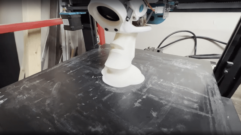
Conceptually, FDM 3D printing is quite a simple process: you define a set of volumes in 3D space, then the slicing software takes a cut through the model at ever-increasing heights, works out where the inner and outer walls are, and then fills in the inside volume sparsely in order to tie the walls together and support the top layers that are added at the end.
But as you will find quite quickly, when models get larger and more complex, printing times can quickly explode. One trick for large models with simple shapes but very low structural needs is to use so-called ‘vase mode’, which traces the outline of the object in a thin, vertical spiral. But this is a weak construction scheme and allows only limited modelling complexity. With that in mind, here’s [Ben Eadie] with a kind-of halfway house technique (video, embedded below) that some might find useful for saving on printing time and material.
The idea is to use vase mode printing, but by manipulating the shell of the model, adding partially cut-through slots around the perimeter, and critically, adding one slot that goes all the way.
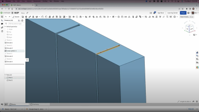
First you need a model that has an inner shell that follows the approximate shape of the outer, which you could produce by hollowing out a solid, leaving a little thickness. By making the slot width equal to half the thickness of the nozzle size and stopping the slots the same distance from the outer shell, vase mode can be used to trace the outline of shape, complete with supporting ribs in between the inner and outer walls of the shell.
Because the slot is narrower than the extrudate, the slot walls will merge together into one solid rib, tying the objects’ walls to each other, but critically, still allowing it to be printed in a continuous spiral without any traditional infill. It’s an interesting idea, that could have some merit.
There are other ways to stiffen up thing printed parts, such as using surface textures, But if you’re fine with the thin shell, but want to have a little fun with it, you can hack the g-code to make some really interesting shapes.


You left out a key detail to understanding how it can print this in vase mode: one of the ribs is “open” on both sides, meaning that the outside and inside are connected together there (and only there). Thus the nozzle can start at that rib, trace around the entire outside, then go inside at that rib, trace along the inside (in the reverse direction), tracing along the inner ribs as they go out towards the outer surface and then back to the inner, and finally going back to the open rib and then going all the way to the outer surface again for the next layer.
That’s probably still not easy to visualize, but it’s explained starting at 3:00 in the video.
No, I think I got that covered:
“adding partially cut-through slots around the perimeter, and critically, adding one slot that goes all the way.”
Nice work Rowndtree I will use this on my 11 in diameter x 11 tall hollow thingy. Ty
I think the problem is that you mentioned the slots before mentioning inner/outer shells. Without any context for the slots, the idea gets lost.
Think of the normal roughly circular path of the vase mode being elongated into a long narrow rectangle with one long side having narrow indents that form the supporting ribs. Now bend the rectangle so the long side without the indents forms the outside perimeter and the short ends of the rectangle almost but not quite touch, and voila!–a doubled-walled “vase” with supporting ribs.
I didn’t really *get* it until I read your reply
I think it’s basically “kerfing” a solid object, except here it’s done during fabrication and not after.
This a neat technique. I’m looking forward to slicers offering it as an automated feature.
This seems like it would be a great mode to add to slicing software, and should be fairly straightforward to implement in code.
This is something I started doing several years ago to generate structure in an efficient manner, minimising travel moves. More recent Model Aircraft designs also use it with light weight filament as it doesn’t like retraction.
https://youtu.be/MQ3f92hDAdY
http//www.youtube.com/CNCModellerUk
I did not have the stamina to look through a 10 minute video for this, but it feels wrong to do this in CAD. but the Idea itself probably works, but it should be built right into the slicer. Just put in some numbers of how thick you want the shell and how inner and outer shell are connected and you’re done.
I use this trick for easy models I made, but if this thing were in slicer for all-thingiverse models it can change 3d printing to better. 2 walls vase without gap gives model lighter abd more durable as 3 normal walls.
Agreed, I’m not a coder and I needed to get the idea out. This is my way of showing it.
I’m sure this will be a feature at some point! It definitely belongs in the slicer. Till then we can do it manually I guess.
I printed a series of vape-pen holders and an armored sleeve (AX2 hard-suit costume project) using a similar technique.
It never occurred to me to make thin ribs as in the article; Brilliant!
My approach was to design the parts as inner and outer shells joined at common openings, forming a lumpy tube.
A single ‘bridge’ (1mm) cut through the side-walls of the tube allows printing the inner and outer shells in one continuous path: Vase Mode.
Imagine printing a large letter “C”; the inner and outer surfaces are are ‘connected’ by the gap.
The ends of the tube have to be designed with care; flat-roofs in Vase mode just don’t work.
All the usual caveats of Vase Mode apply; no supports, watch your over-hangs.
The space between the shells (about 6mm for the armor) and their non-matching compound curves made the parts quite rigid without being heavy or taking forever to print. PETG all the way.
After printing, the ends of the tubes were closed with printed slip-ring bearings; this helped hold the gaps closed and allowed surprisingly easy movement.
Robert is your parents sibling.
Ooops!
Forgot to leave a pointer to the AX2 hard-suit files!
Search “AX2 hard suit stl files” in yer broswer, they are hosted on the amazing Prusa site!
https://www.printables.com/search/models?q=ax2%20hard%20suit ?
No results.
Very cool! He basically used corrugation!
Is the lightest and strongest print to be had if the infill is an Apollonian gasket?
I wonder if the strongest and lightest form is to be had by using a space filling pattern that approximates to Apollonian Sphere Packing? The best reference I can find so far is, Bonneau, F., Scholtès, L. & Rambure, H. An algorithm for generating mechanically sound sphere packings in geological models. Comp. Part. Mech. 8, 201–214 (2021).
I’m with the commenters who write “this should be in the slicer”, but until it gets picked up, this is a neat workaround.
Reminds me of the old trick of putting interior voids into a print (“drilling” it internally) to fool the slicer into making strong (N-perimeter) pillars internally where it’s needed. Or just-under-one-layer webs to serve as support for otherwise impossible overhangs.
https://hackaday.com/2017/10/17/sacrificial-bridge-avoids-3d-printed-supports/
https://hackaday.com/2020/05/17/look-ma-no-support-for-my-floating-holes/
We use lots of tricks in the model to trick the slicer into doing what we want. Why? Because our modeling software and the files it produces are meant to be uniform.
Gerrit touched on it well in this great think-piece about how you could sneak design intent into 3D files:
https://hackaday.com/2016/04/07/a-look-into-the-future-of-slicing/
(Which has actually aged pretty well!)
As others have said, it’s best in the slicer. But in the meantime it could be pre-slicer, processing the STL.
A better name for this process might be “Vase Corrugation”, “Vase Mode Corrugation” or for the shell version “Vase Shell Corrugation”.
I’m glad I found this after only spending a few hours looking into making my own slicer. Coming from a CNC background I would ramp on z moves whenever I could for a smoother cut. With seems being such an issue with 3D printing I didn’t understand why vase mode was so limited in the slicer. I really expect this to end up in some slicers or to hear some good explanations why it isn’t.
Can you elaborate on those Z ramps? I’m not really familiar with CNC milling techniques. And how do seams and vase mode relate to each other (and maybe to the Z ramps)?