When you’re a machinist, your stock in trade is precision, with measurements in the thousandths of your preferred unit being common. But when you’re a diemaker, your precision game needs to be even finer, and being able to position tools and material with seemingly impossibly granularity becomes really important.
For [Adam Demuth], aka “Adam the Machinist” on YouTube, the need for ultra-fine resolution machinist’s jacks that wouldn’t break the bank led to a design using off-the-shelf hardware and some 3D printed parts. The design centers around an inch-metric thread adapter that you can pick up from McMaster-Carr. The female thread on the adapter is an M8-1.25, while the male side is a 5/8″-16 thread. The pitches of these threads are very close to each other — only 0.0063″, or 161 microns. To take advantage of this, [Adam] printed a cage with compliant mechanism springs; the cage holds the threaded parts together and provide axial preload to remove backlash, and allows mounting of precision steel balls at each end to make sure the force of the jack is transmitted through a single point at each end. Each full turn of the jack moves the ends by the pitch difference, leading to ultra-fine resolution positioning. Need even more precision? Try an M5 to 10-32 adapter for about 6 microns per revolution!
While we’ve seen different thread pitches used for fine positioning before, [Adam]’s approach needs to machining. And as useful as these jacks are on their own, [Adam] stepped things up by using three of them to make a kinematic base, which is finely adjustable in three axes. It’s not quite a nanopositioning Stewart platform, but you could see how adding three more jacks and some actuators could make that happen.


Adam is the real deal in the world of ultra-precision diemaking and metalworking. He typically uses time-tested methods to produce stamping dies with ±0.0001″ tolerances, but his recent forays into innovative positioning solutions utilizing differential threads and gearing and 3D printing are worth checking out.
Ingenious!
Shouldn’t that be 5/8″-18?
Ackshully…. pretty sure this is a typo. Dan means to say this uses a 5/16″-18 x M8 x 1.25 thread adapter. Adam says so in the video.
How consistent is the thread pitch though? Axial alignment? The idea is sound, but the manufacturing of these off-the-shelf parts isn’t necessarily nice enough to warrant the claims of precision to tens of microns. Hundreds of microns I can believe since you can check that much with a vernier caliper.
yeah, through I guess with proper calibration this should be good…. the idea is definitely brilliant and I guess you can have the parts custom made if you want more precision through that ain’t cheap anymore…
also if you’re into that kind of precision you probably do no want to touch the metal nut with your hands without some kind of isolation, like the plastic flange on micrometers…
Are you saying ‘human fingers are too clumsy for that level of precision’ or ‘human fingers are too dirty/conductive?/whatever and will throw off the mechanism’? Asking out of curiosity/ignorance.
Heat from your fingers expands the metal and it’s measurable at this level
You go through a pile of nuts and find a segment which happens to have a very linear and snug revolution or three under test. I expect that for this kind of precision, you aren’t looking for it to last through the entire nut. It’s a cheap hack, after all.
The mismatch of metric and imperial is genius, you have to at least hand him that.
if the purpose is just to move things in fine increments it doesn’t matter if it absolute accurate
It makes sense, that’s why he can use 3D printed parts which don’t have that much precision at all.
A spring that pulls off the backlash doesn’t need precision.
I don’t think that a consistent thread pitch is that important, where I see this mechanism interesting, you want to be able to make small movement and not an absolute precise movement.
You would use a dial indicator for example or any measuring devise which gives you the precision needed and would turn the screw until you’re where you want it to be. The moment it doesn’t drift from it’s position for whatever reason, then it’s ok.
But I agree that the axial alignement problem isn’t solved if used as is. I would use this system with a linear rail or a precision bushing, then the misalignment isn’t that much of a problem anymore, it just induces some error that would be compensated with the aforementioned method.
Tldr: this system allows small movement, another system should handle the precise linear or rotating movement.
With the number of threads engaged being sufficient it doesn’t matter if the pitch is all over the place within specs enough they actually fit each other – the bolt and nut will always have points in contact at the correct pitch – and because its being used under tension all the time any slop in the threads doesn’t matter either – its permanently loaded against one side.
Axial alignment should also be sufficient with enough engagement as well – as again it can’t actually get all that far out of ideal and actually thread on across so many threads… Though there is more scope for error there, plus the entire length even if mystically perfectly parallel to itself is long enough cosine error from the surface will really add up meaningfully.
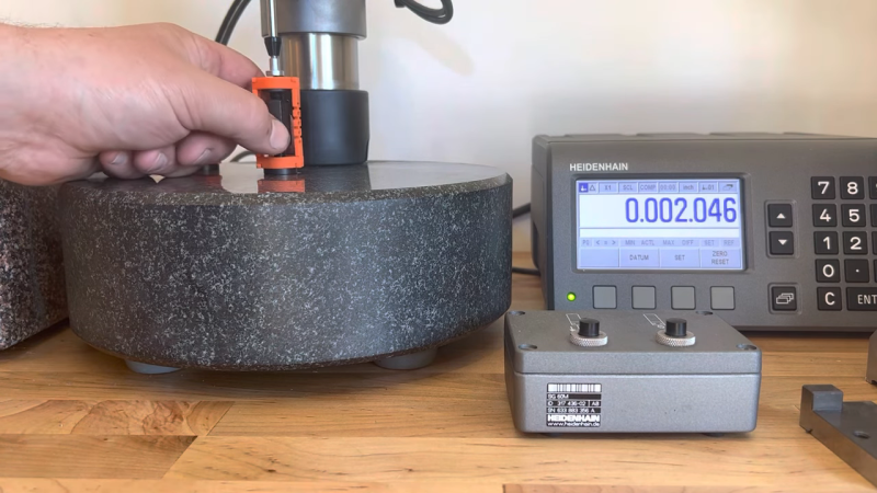
Its all averaging out the lower precision parts/surfaces into a more consistent result, or as the banner image shows using the fine adjustment potential against a trusted measure to set the length precisely…
>its permanently loaded against one side
If the two threads aren’t cut closely along the same axis, then this will not be the case. The actual contact point will shift around the perimeter.
“before, [Adam]’s approach needs to machining.”
Wut?
This obviously should be “needs no machining”
As briefly mentioned in the video, This would be great for optical experimentation. I do wonder how far this could be taken. Perhaps adding some sort of lever to increase the resolution or maybe even one of those tiny linear servos used in hobby aircraft to rotate the nut in a more repeatable, automated and isolated fashion. No doubt fine adjustment of laser phase is now within closer reach of those of us working on a tight budget.
If you want to move them electronically why not piezo? That’s how tunneling electron microscopes position. Can’t get more precise than that, Planck says so.