Tensioning 3D Prints For Lightweight, Strong Parts

Desktop 3D printers have come a long way over the past decade. They’re now affordable for almost anyone, capable of printing in many diverse materials, and offer a level of rapid prototyping and development not feasible with other methods. That said, the fact that they are largely limited to printing different formulations of plastic means there are inherent physical limitations to what the machines are capable of, largely because they print almost exclusively in plastic. But augmenting prints with other building techniques, like this method for adding tensioning systems to 3D printed trusses can save weight and make otherwise unremarkable prints incredibly strong.

The build from [Jón Schone] of Proper Printing consists of printed modular sections of truss which can be connected together to make structural components of arbitrary length. To add strength to them without weight, a series of Kevlar threads are strung from one end of the truss to the other on the interior, and then tensioned by twisting the threads at one end. Similar to building with prestressed concrete, this method allows for stronger parts, longer spans, less building material, and lighter weight components. The latter of which is especially important here, because this method is planned for use to eventually build a 3D printer where the components need to be light and strong. In this build it’s being used to make a desk lamp with a hinged joint.

For other innovative 3D printer builds, [Jón] has plenty of interesting designs ranging from this dual extrusion system to this 3D printed wheel for a full-size passenger vehicle. There’s all kinds of interesting stuff going on at that channel and we’ll be on the edge of our seats waiting to see the 3D printer he builds using this tensioned truss system.

Continue reading “Tensioning 3D Prints For Lightweight, Strong Parts”

3D Printed Machine Shows How Braiding Is Done

If there’s something more fascinating than watching cleverly engineered industrial machines do their work, we don’t know what it could be. And at the top of that list has to be the machines that do braiding. You’ve probably seen them, with spools of thread or wire dancing under and around each other in an endless ballet that somehow manages to weave a perfect braid. It’s kind of magical.

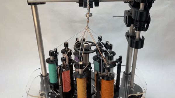
For those who haven’t seen such a thing, now’s your chance, with this twelve-spool braiding machine. The building methods that [Fraens] used — mainly 3D printing and laser-cut acrylic — make the workings on this machine plain, even to those of us who never learned to manually braid even three strands. It’s far easier to understand by watching the video below than by trying to describe it, but basically, each vertical supply spool runs along a continuous track around a central point by a series of six meshed gears, passing under each other as they progress around the carousel and forming the braid.

There are a ton of details that go into making this work. Chief among them is the thread tensioning mechanism, which is a lever arm and spring-loaded axle that lives at the very center of each spool. The gears that form the inside-outside tracks are quite clever too, as are the worm-gear-driven takeup reel and output tensioner. We also appreciated the gate used to load the spool carriers into the track.

We can recall a couple of braiding machines before, including this one made entirely from Lego Technics.

Continue reading “3D Printed Machine Shows How Braiding Is Done”

The Nuts And Bolts Of Nuts And Bolts

If you’re a mechanical engineer, the material covered in this video on the basics of bolted joints probably won’t cover any new ground. On the other hand, if you aren’t a mechanical engineer but still need to bring a little of that discipline to your projects, there’s a lot to learn here.

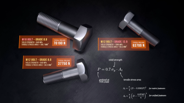
If there’s one takeaway lesson from [The Efficient Engineer]’s excellent examination of the strength of bolted joints, it’s the importance of preload. Preload is the tensile force created by tightening a bolt or a screw, which provides the clamping force that keeps the joined members together. That seems pretty self-obvious, but there’s more to the story, especially with joints that are subject to cycles or loading and unloading. Such joints tend to suffer from fatigue failure, but proper preloading on the bolts in such a joint mitigates fatigue failure because the bolts are only taking up a small fraction of the total cyclical force on the joint. In other words, make sure you pay attention to factory torque specs.

Continue reading “The Nuts And Bolts Of Nuts And Bolts”

The Goalie Mask, Reenvisioned

The goalie mask, at least the retro-styled fiberglass types from the 60s and 70s, hasn’t been used in hockey for about 50 years —  it’s instead made many more appearances in horror movies than on ice rinks. Since then, though, there’s been very little innovation surrounding the goalie mask even though there’s much more modern technology that could theoretically give them even greater visibility. [Surjan Singh] is hoping to use his engineering and hockey backgrounds to finally drive some improvements.

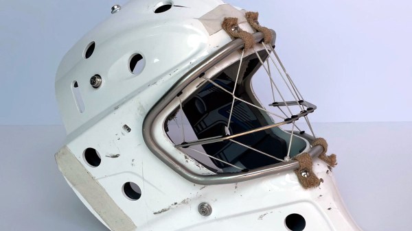
The “uncage” is based on Dyneema thread, a polyethylene fiber known for its strength and durability. It’s often used in applications that demand high strength with minimal weight, such as for sails or backpacking equipment. Using strands of Dyneema woven through a metal support structure is what gives this mask its high strength while also improving the visibility through it dramatically. [Surjan] has been prototyping this design extensively, as there were some issues with the fibers chafing on attachment points on the metal frame, but most of these issues have been ironed out or are being worked on currently.

In the meantime, [Surjan] has been looking for a professional-level goalie to help refine his design further and does seem to have some interest, but it doesn’t seem to have progressed past testing in the more controlled test environments yet. It’s not too far-fetched to imagine this as the future of goalie masks in professional hockey though since some innovation after 50 years of relative stagnation seems to be due. For something more accessible to those of us not currently playing in the NHL, though, you can wheel, snipe, and celly on this air hockey table instead.

Continue reading “The Goalie Mask, Reenvisioned”

Metric And Inch Threads Fight It Out For Ultra-Precise Positioning

When you’re a machinist, your stock in trade is precision, with measurements in the thousandths of your preferred unit being common. But when you’re a diemaker, your precision game needs to be even finer, and being able to position tools and material with seemingly impossibly granularity becomes really important.

For [Adam Demuth], aka “Adam the Machinist” on YouTube, the need for ultra-fine resolution machinist’s jacks that wouldn’t break the bank led to a design using off-the-shelf hardware and some 3D printed parts. The design centers around an inch-metric thread adapter that you can pick up from McMaster-Carr. The female thread on the adapter is an M8-1.25, while the male side is a 5/8″-16 thread. The pitches of these threads are very close to each other — only 0.0063″, or 161 microns. To take advantage of this, [Adam] printed a cage with compliant mechanism springs; the cage holds the threaded parts together and provide axial preload to remove backlash, and allows mounting of precision steel balls at each end to make sure the force of the jack is transmitted through a single point at each end. Each full turn of the jack moves the ends by the pitch difference, leading to ultra-fine resolution positioning. Need even more precision? Try an M5 to 10-32 adapter for about 6 microns per revolution!

While we’ve seen different thread pitches used for fine positioning before, [Adam]’s approach needs to machining. And as useful as these jacks are on their own, [Adam] stepped things up by using three of them to make a kinematic base, which is finely adjustable in three axes. It’s not quite a nanopositioning Stewart platform, but you could see how adding three more jacks and some actuators could make that happen.

Continue reading “Metric And Inch Threads Fight It Out For Ultra-Precise Positioning”

Fork And Run: The Definitive Guide To Getting Started With Multiprocessing

Since the early 2000s, the CPU industry has shifted from raw clock speed to core counts. Pat Gelsinger famously took the stage in 2002 and gave the talk the industry needed, stating processors needed specialty silicon or multiple cores to reduce power requirements and spread heat. A few years later, the Core series was introduced with two or four-core configurations to compete with the AMD Athlon 64 x2.

Nowadays, we’re seeing heterogeneous chip designs with big and little cores, chiplets, and other crazy fabrication techniques that are fundamentally the same concept: spread the thermal load across multiple pieces of silicon. This writer is willing to put good money into betting that you’ll see consumer desktop machines with 32 physical cores in less than five years. It might be hard to believe, but a 2013 Intel Haswell i7 came with just four cores compared to the twenty you’ll get in an i7 today. Even an ESP32 has two cores with support in FreeRTOS for pinning tasks to different cores. With so many cores, how to even write software for that? What’s the difference between processes and threads? How does this all work in straight vanilla C98?

Continue reading “Fork And Run: The Definitive Guide To Getting Started With Multiprocessing”

spinning thread extruder

Spinning Threads Put The Bite On Filament In This Novel Extruder Design

When it comes to innovation in FDM 3D printing, there doesn’t seem to be much room left to move the needle. Pretty much everything about filament printing has been reduced to practice, with more or less every assembly available off the shelf. Even the business end — the extruder — is so optimized that there’s not much room left for innovation.

Or is there? The way [David Leitner] sees it, there is, which is why he built this rolling-screw extruder (if you can get to the Thingiverse link, [David] cross-posted on reddit, too). Standard extruders work on the pinch-roller principle, where the relatively soft filament is fed past a spring-loaded gear attached to a stepper motor. The stepper rotates the gear, which either advances the filament into or retracts it from the hot end. [David]’s design instead uses a trio of threaded rods mounted between two rings. The rods are at an angle relative to the central axis of the rings, forming a passage that’s just the right size for the filament to fit in. When the rings spin, the threads on the rods engage with the filament, gripping it around its whole circumference and advancing or retracting it depending on which way it’s spinning. The video below shows it working; we have to admit it’s pretty mesmerizing to watch.

[David] himself admits there’s not much advantage to it, perhaps other than a lower tendency to skip since the force is spread over the entire surface of the filament rather than just a small pinch point. Regardless, we like the kind of thinking that leads to something like this, and we’ll bet there are probably unseen benefits to it. And maybe the extruder actually is a place for innovation after all; witness this modular nozzle swapping system.

Continue reading “Spinning Threads Put The Bite On Filament In This Novel Extruder Design”