Most multi-rotor aircraft are about as aerodynamic as a brick. Unless all its motors are turning and the control electronics are doing their thing, most UAVs are quickly destined to become UGVs, and generally in spectacular fashion. But by switching up things a bit, it’s possible to make a multi-rotor drone that keeps on flying even without two-thirds of its motors running.
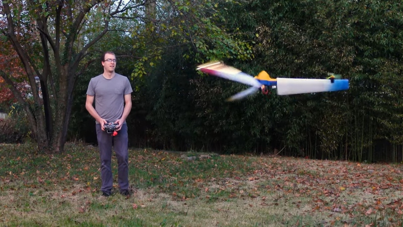
We’ve been keeping a close eye on [Nick Rehm]’s cool spinning drone project, which basically eschews a rigid airframe for a set of three airfoils joined to a central hub. The collective pitch of the blades can be controlled via a servo in the hub, and the whole thing can be made to rotate and provide lift thanks to the thrust of tip-mounted motors and props. We’ve seen [Nick] manage to get this contraption airborne, and hovering is pretty straightforward. The video below covers the next step: getting pitch, roll, and yaw control over the spinning blades of doom.
The problem isn’t trivial. First off, [Nick] had to decide what the front of a spinning aircraft even means. Through the clever uses of LED strips mounted to the airfoils and some POV magic, he was able to visually indicate a reference axis. From there he was able to come up with a scheme to vary the power to each motor as it moves relative to the reference axis, modulating it in either a sine or cosine function to achieve roll and pitch control. This basically imitates the cyclic pitch control of a classic helicopter — a sort of virtual swashplate.
The results of all this are impressive, if a bit terrifying. [Nick] clearly has control of the aircraft even though it’s spinning at 250 RPM, but even cooler is the bit where he kills first one then two motors. It struggles, but it’s still controllable enough for a bumpy but safe landing.


Unmanned G??? Vehicle?
From UAV (Unmanned Aerial Vehicule) to UGV (Unmanned Ground Vehicule), one way or an other, in a controlled way or not, ….
Probable “Ground”, as in, no longer flying
https://en.wikipedia.org/wiki/Unmanned_ground_vehicle
See: lithobraking.
Pretty cool. To fix the camera issue you could just modulate the exposure control to an even multiple of the rpm. Similar to how the LEDs turn on at a specific time point, you would trigger the exposure at that point in time.
The shutter speed would need to be very fast to counteract the motion blur.
I have seen that done by some research group, taking one picture every revolution and even stitching a 360 degree view out of it, but I can’t remember where or by whom.
or use global shutter sensor
Same principle for the “machine gun through the propeller” trick they did back in the early days of air combat.
Seems like there might be a bit too much drift for that to really work, I expect the pilot would feel rather like flying a bucking bronco with it drifting around in its idea of what ‘forward’ is so much, probably made worse by the frame latency likely being a bit all over the place – which I’d expect as the whole lot spins for variable connection quality (though is this a digital or analog stream?? The latter might look awful but shouldn’t pose as many problems). Its a good idea I don’t think this iteration can really make work, though I’d love to be proven wrong.
Seems to me though the simpler option to add to this thing is a camera pod that can drive itself relative to the rotor hub – keeps all the video electronics together and hopefully consistent in signal, might smooth out the drift feeling at little too as the inertia of the camera can only be changed so fast, in effect a bit of real world motion smoothing..
You could use a single line sensor, facing out from the hub, and build a panoramic image from vertical slices as the craft rotates. Stabilize it and cut out whatever chunk you want to send to the FPV display. Tracking the pilot’s head would make it even more intuitive.
It would have a mad rolling shutter effect.
Wouldn’t you have an exposure time issue? Even if you have a shutter of 1ms, in that time, the camera would rotate 1.5 degree, making for blurry dark pictures (as 1ms shutter is really short)
Around 6m10s in the video, there’s a really cool artifact caused by the propeller chopping the light from the LED strip, interacting with the camera’s rolling shutter. I’d love to get the Slow-Mo guys on this!
I’m curious as to what set of requirements drove the 250 RPM rotational rate.
It was less of a requirement and more of a finding after building and flight testing–250 RPM is the sweet spot for this design’s efficiency when spinning
How about a platform that only requires one motor and two small actuators with no complex mechanism like a swashplate.
So instead of three tip motors/props, use one large motor which drives two large counter-rotating co-axial rotors. Control would be accomplished with two servos that dynamically actuate servo flaps in-sync with rotor phase. The servos wouldn’t require as much power as you think since they could operate like the Kaman K-MAX main rotor blades AKA Kaman “Servo Flap”. In that configuration the rotor is fixed with no pitch or swash-plate mechanism. An adjustable flap at the rotor tip causes rotor twist/pitch proportional to the servo flap angle. Since this twisting force is not coming directly from the flap actuator, but rather the main rotor’s movement through the air, a relatively small and fast electronic actuator can be used.
It has pitch, roll, collective and yaw is relative. If you want a camera platform, just hang it from a pivot and use the down wash to counter any residual torque.