Over the last couple years, we’ve seen an absolute explosion of masked stereolithography (MSLA) 3D printers that use an LCD screen to selectively block UV light coming from a powerful LED array. Combined with a stepper motor that gradually lifts the build plate away from the screen, this arrangement can be used to produce high-resolution 3D prints out of photosensitive resins. The machines are cheap, relatively simple, and the end results can be phenomenal.
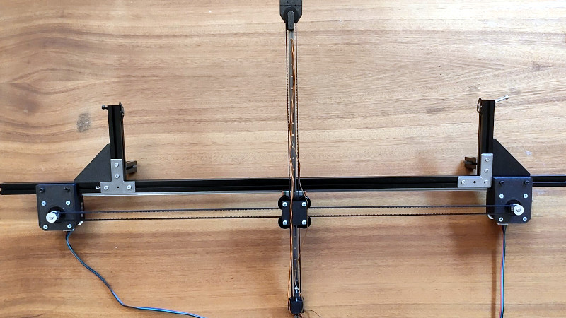
But they aren’t foolproof. As [Jan Mrázek] explains, these printers are only as good as their optical setup — if they don’t have a consistent UV light source, or the masking LCD isn’t working properly, the final printed part will suffer. In an effort to better understand how these factors impact print quality, he designed the DrLCD: a TSL2561 luminosity sensor mounted to a robotic arm with associated software to map out the printer’s light source.
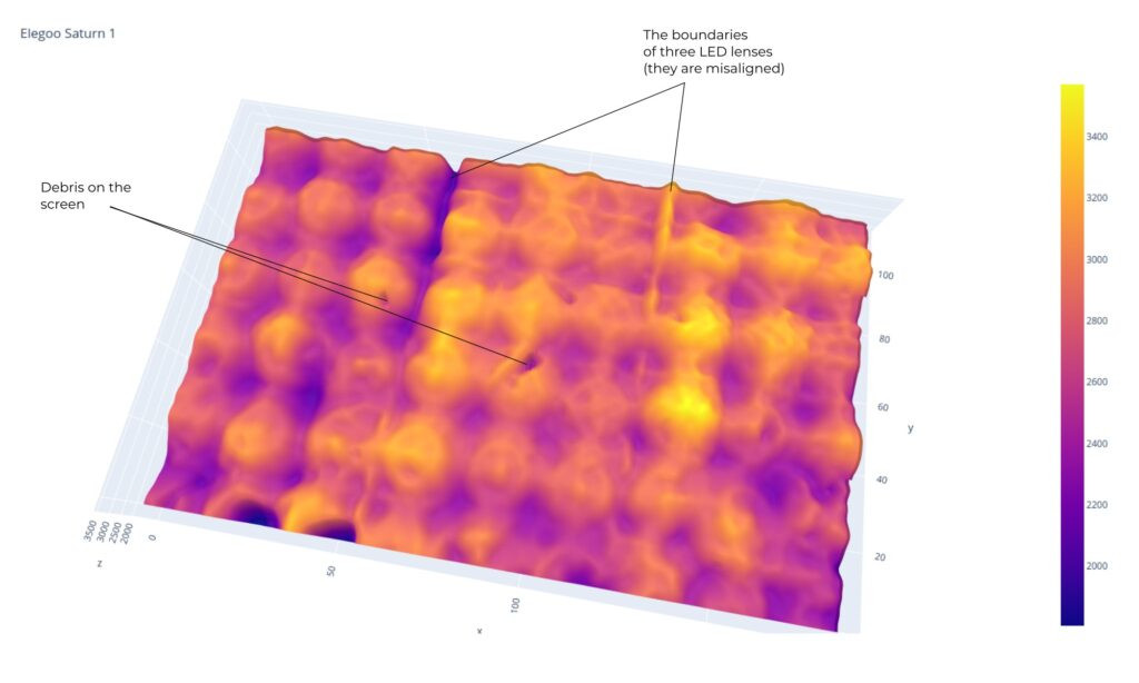
The results when running DrLCD against a few different types of printers is fascinating. [Jan] was clearly able to make out the type of lenses used, and in one case, was even able to detect that a darker spot in the scan was due to a bit of resin having leaked into the light source and clouded up the optics.
But DrLCD can do more than just tell you where you’ve got a dark spot. Using the data collected from the scan, it’s possible to create a “compensation map” that can be combined with the sliced model you wish to print. As the slicer assumes an idealistic light source, this map can help by adding additional masking where bright spots in the display have been detected.
[Jan] goes on to compare the dimensional accuracy of printed parts before and after the compensation map has been applied to the model, and was able to identify a small but distinctive improvement. Not everyone is going to be concerned about the 157 µm deviation observed without the backlight compensation, but we certainly aren’t going to complain about 3D printers getting even more dimensionally accurate.
A couple years back we covered a similar technique that used a DSLR to capture high-resolution images of the bed. While arguably much easier to pull off, we can’t help but fall in love with the glorious overengineering that went into the DrLCD system, and we can’t wait until it starts making house calls.


Maybe you could use the generated image to print a physical compensation mask on a sheet of transparency. It would darken the bright spots evening out the light.
I am afraid that you cannot do that on consumer printer. Even a 1200 DPI printer can print dots that are 20 µm in size. That is practically the size of a single pixel of the modern LCDs (28 µm). You gain nearly nothing as you would either completely shadow a pixel or not.
It’s actually not a bad idea if you place the transparency some distance away from the LCD so that the dots are out of focus. Not so sure how well it’ll stand up to UV though. Microlens arrays are pretty much the gold standard for light source uniformity but are currently very $$$.
I’ve done that. It roughly works, but digital corrections will have far better quality not to mention more practical.
The correction should take place in the printer, not in the slicer. The slicer produces 1bit B/W images. But the TFT in the printer can of course do more than 1bit color depth.
Are there open source controllers for MSLA printers available? I built all my FDM controllers and printers from parts, but I never cared with MSLA, I just used it out of the box.
You are right that it should be supported by the printer, but the current closed ecosystems doesn’t allow for that. There is no proper open-source solution (yet), but there could be (e.g., Athena).
The slicer produces grayscale image to allow for sub-pixel curing (details in the blog post). And you can use it to fix current printers running the closed ecosystem.
For context: one of the biggest issues with an open source controller is the screen interface. Since the printer is basically a screen, LED, and a Z-axis.
The problem is, most screens use a proprietary interface technology that requires a multimillion dollar license to even use.
However, I think I heard of a recent screen that connected over a much more common interface, like HDMI or Display port, or something. At which point, running everything off a RasPi or similar would be quite simple.
Ah, found it: in another blog post, Jan says that the screen of the Saturn 2 uses eDP (embedded DisplayPort). I don’t know if there are any cheap boards that can output eDP at 8K resolution, but, if there are, then it’d be great to finally start building open source resin printers and software.
https://blog.honzamrazek.cz/2022/10/elegoo-saturn-2-review-is-pixel-size-everything-in-depth-look-disassembly/
Can you not just stick a sheet of photo paper in it, expose it for 1/250 or so and see how blotchy that looks when developed?
That’s pretty clever. Maybe not as cool, but certainly elegant.
Thank you for this article. It certainly brings new ideas to the table. The photo paper idea is fantastic too.
Maybe use the photo paper as a basic functionality test, and then DrLCD as a way to build a compensation algorithm for fine tuning.
The DrLCD results would be most beneficial as a direct firmware correction, as it would vary printer to printer. Once it’s set, keep the printer clean and run with it.
It would be cool to see a printer comparison using this new technology too. Keep up the great work!
This method allows you to compensate for the unevenness.