Most readers will be familiar with Ethernet networks in some form, in particular the Cat5 cables which may snake around the back of our benches. In a similar vein, we’ll have used power over Ethernet, or PoE, to power devices such as webcams. Buy a PoE router or switch, plug in a cable, and away you go! But what lies behind PoE, and how does it work? [Alan] has written a comprehensive guide, based on experience working with the technology.
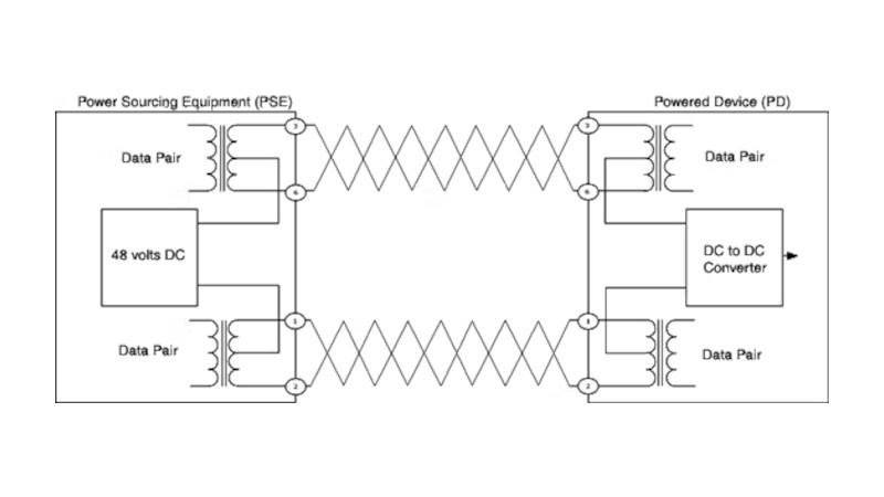
What we get first is a run-down of the various topographies involved. Then [Alan] dives into the way a PoE port polls for a PoE device to be connected, identifies it, and ramps up the voltage. Explaining the various different circuits is particularly valuable. The final part of the show deals with the design of a PoE module, with a small switching power supply to give the required 48 volts.
All in all, this should be required reading for anyone who works with Ethernet, because it’s one of those things too often presented as something of a black box. If you’re thirsty for more, it’s a subject Hackaday have touched on too in the past.


Ah the magic of the center tap
Not as good as a beer tap.
If the coil is only 2 turns as in picture then it should not have much effect on 48 VDC, same voltage is used on a***og phone lines.
Gosh, what non-digital words you use that the system had to censor…
Such a pot-mouth.
*POTS-mouth
…
Sorry I had to
In the analogue world you need about 2 turns per volt or bad things happen like really bad non-digital bad analogue smoky things. Because, analogue is still hiding in there within digital signals – it never goes away because it’s a recognition of the laws of physics and one dose not simply change the laws of physics.
That’s why you always see a seriously analogue multi transformer block on network cards. They haven’t made digital transformers yet because the energy required to make the transformer go from totally off to totally on in an instant would consume the universe (or more likely make the transformer explode). But I ‘spose that is actually digital as in binary – either the transformer is there or it’s gone leaving only a wisp of magic smoke – but yeah, very low data rates if you want to do digital that way. Kinda like Schrödinger’s cat.
What you see in the image is a diagram. If the transformer had 1000 turns, do you think they should be drawn? It’s just a representation…
But far better than a spinal tap.
Here’s hoping I can run my internet-connected arc welder over it.
Add it to home assistant and automatically change settings based on temperature and humidity. I see options.
Wouldn’t work because technically it would be IoT device so it will have to go via a server in another country that is always running at 2000% load capacity so when you pull the trigger the IoT will have to make 20 requests taking about 45 seconds before one is successful and the arc starts.
XD
This is so true it hurts.
Alexa, stop welding.
Alexa, please stop welding.
ALEXA STOP WELDING!
Most (all?) PoE interfaces that I’ve looked at use a flyback converter – I guess that the main goal is galvanic isolation. But the typical use-cases for PoE such as wireless routers or IP cameras have no need for galvanic isolation, these devices will not be physically connected to anything other than the ethernet cable. Is there any other reason for the isolated DC/DC converter?
There are various cheap “not-quite-PoE” adapters which simply pass the DC voltage on the unused pairs of 100Mbit ethernet, offering no isolation. Are there any reasonable conditions under which these would cause trouble?
Aside from blowing stuff up that doesn’t expect the voltage it seems unlikely.
Not quite PoE adapters are isolated because the only connectors are the mains PSU(isolated, I hope), the Ethernet to the switch(Presumably isolated at the switch, if not also at the not-quite-poe adapter), and the output.
Hard to imagine a ground loop happening if used as intended. I still would prefer real PoE because misuse is not exactly unlikely, and there could be problems I haven’t thought of.
Multiport switches need the isolation because they have multiple ports. If two weren’t isolated, and power two things that themselves don’t have isolation, and you connect those things via USB or 3.5mm or something, you get a ground loop.
This may be specific to my country? I had a system fail on a large site because there were two incoming mains supplies.
One was single phase and it was all ok.
The other feed in was three phase star “Y” to drive a exceptionally large kitchen that could cater for several hundred guests and some very large industrial air conditioners so it had very high current draw in total with no predictability as to which phase would have more current at any given time so the neutral or the cetre of the star or “Y” had 36VAC (above acceptable limits) and that drowned out the low level data signals.
Now this wasn’t a cat5 system but it shows why you need signal isolation.
Even with cat5, you may have a POE RS-485 converter at the other end connected to lots of devices that have their own earth.
The other reason to use a fly-back converter is that it’s easier to design for a large ratio of input to output voltage than a Buck converter. Also prevents accidental ground loops and picking up ground currents on equipment that is grounded.
Good explanation! Thanks.
I’m not entirely convinced that this is a flyback transformer. Flybacks are best for high voltages at very low currents. The size of a flyback transformer increases rapidly with the current requirements.
You can achieve the same level of isolation with a non-flyback or normal type of transformer you just need to opto-couple the voltage regulation feedback.
If I risk an “OK Boomer” by writing about the forbidden analogue – this is the difference –
In a flyback the primary is quickly driven to high flux, which means it’s need a high inductance (lots of windings, making it much larger) or it would get very very smoky hot.
Then the primary is essentially disconnected and the magnetic field collapses creating a very high Back EMF (reflected electro motive force) which is much higher in voltage (6 times or more) then a coupled transformer. And this goes through ONLY one diode (apart from potentially a voltage multiplyer but that is after that one diode) because the secondary ONLY receives power when the primary is NOT being driven (this is the defining feature of a flyback system). The primary only drives the transformer and it never “feels” the load because it is not electro-magnetically coupled to the load. It always starts with a collapsed magnetic field (no field) regardless of the load so a dead short circuit on the load after the one secondary diode would have absolutely no effect on the primary or primary driver circuitry – no increase of current into the transformer.
Alternatively –
In a coupled transformer system the secondary receives power when the primary IS being driven and quite (most) often the primary is alternately driven in both polarities and there are 2 diodes to 4 diodes on the secondary. The primary IS magnetically coupled to the secondary and in increase of secondary load will cause more current in the primary drive in most circuits.
Both of these systems can be designed to provide the same level of isolation however one is complex and expensive (flyback transformer) and the other is simpler and cheaper (unless your buying junk from China.
And to clarify further. There is a type of BOTH non-flyback coupled transformer AND flayback transformer or whatever else transformer called an auto-transformer and in this type if transformer there is NO isolation because one side of the primary is directly connected to one side of the secondary. I say this because people think of old CRT TVs and the flyback transformer in then that is often also a auto-transformer and they should more correctly be called a LOPT Line OutPut Transformer.
OK, now back to my booming!
” DC voltage on the unused pairs of 100Mbit ethernet, offering no isolation. Are there any reasonable conditions under which these would cause trouble? ”
Yes, on 1 Gbit Ethernet. All pairs are used.
Putting uncontrolled 48V on the unused pairs of a 10/100 link will cause smoke if plugged into a 10/100 Ethernet product. The unused pairs are terminated inside the Ethernet product – typically with 75 Ohm to chassis on each wire. 48V / 75 Ohm = smoke. Your device will probably keep working fine and will eventually stop smoking when the resistors burn out but I wouldn’t do it.
Big Big belly laugh!!!
48V / 75 Ohm = smoke
Your math seems incomplete , what are the units of smoke? Cubic foot per minute? Litres per second and what is the quantity lol :)
No it’s not needed as long as no metal is exposed (eg antenna connector, …)
57V to 3.3V with a buck converter will result in a very small duty cycle, likely making a small transformer desirable anyway. And then a flyback is a good option, even if you don’t use the galvanic isolation property (and indeed, there are devices that omit the opto-coupler, while still using a flyback PoE supply)
The reason is the resistance of the cable (ohms/meter), otherwise, the voltage drop would be enormous, depending on the length of the cable.
Ok, question, i am designing an Arduino shield with enc28j60 and i want to add passive PoE with place to add voltage converter (there will be a place for LM7805, popular LM2596 board and other options to add voltage converter, when done i will share it with the world).
My goal is to use most generic components for the board so it will be eaisly available and i have question about connecting the RJ45 connector to the magnetics, can i leave pin 7 and 8 of the magnetics disconnected?
Please see picture attached below:
https://drive.google.com/file/d/1Xc-gw21uE5UzlV73k_la8rbm2BtzXCqB/view?usp=sharing
I am going to test it anyway around christmas but i wish to know your opinion.
Buy a pre made pennies on the dollar solution and stop fretting about it.
I would, belive me, but there is no PoE shield for uno/mega with enc28j60.
I started to read over the info presented, and it’s flat out WRONG on at least 2 points based on a cursory and incomplete reading.
1) It defines endspan and midspan incorrectly.
It defines midspan as POE carried over non-signalling wires in 10/100 installations. This is more properly called passive POE (or not-really POE).
It defines endspan as POE where the signalling wires are used to carry power as well, such as in gigabit installations. This is more properly called active POE (or actually POE :-)).
Endspan and midspan refer to where the PSE (power sourcing equipment) sits in the cable plant. Is it integrated with the switch? (Endspan) or is it a separate adapter that is somewhere in the middle of the cable span (midspan).
2) Defines T568A and T568B as related to their (incorrect) definition of endspan and midspan.
T568 refers to the ordering of pairs in an RJ45 jack or plug.
A) white-green/green/white-orange/blue/white-blue/orange/white-brown/brown
B) white-orange/orange/white-green/blue/white-blue/green/white-brown/brown
This was used back in the olden days when equipment didn’t all come in auto-crossover (seriously, it’s been years since I’ve seen any newly produced equipment without auto-mdx). If you needed to connect 2 switches or hubs together. You’d make (or buy) a cable with the signalling pairs swapped (one side T568A one side T568B) so the input pair on one device connected to the output pair on the other, and vice versa.
—————-
Once I reached this point, I stopped reading. When the very basics are this wrong, I cannot trust the rest.
A little harsh, maybe.
The figure lifted from Versatek seems to suggest T568A and T568B are linked to 802.af Mode A and Mode B. (The article that is the source for this figure is at https://www.versatek.com/what-is-power-over-ethernet/ ). I have no idea if this is truly the case, I can’t see why the two would be linked.
Midspan power injectors are much simpler to implement using 802.af Mode B so 802.af mode A is associated with endspan POE and 802.af mode B is associated with midspan POE. See for example, the Wikipedia entry for POE.
The history goes back a lot further right back to early POTS (Plain Old Telephone system).
The plug you call a RJ45 plug isn’t a RJ45 plug because the J in RJ45 stands for Jack (socket).
The plug started as a 4 Position 2 Conductor (4P2C) telephone plug then in various stages it progress to 6P4C (for phones) and the first ever pair on the 4P2C was put in the middle so the second in the 4P4C went on the outside of that so that system was extended with to the 8P8C with one extra pair on each side – so the outer ones together on the sides and the middle one together on one split at positions 4 and 5.
Midspan and endspan can easily seem ambiguous in data networks.
A PoE switch with a feed going north and a feed going south, obvious? No, the network topology may be completely different to the physical topology especially with PoE pass through.
So if someone wants to ague that then I will concede defeat at the onset as that could be a long augment that takes a lot of research today.
Whilst I haven’t read the OP, what’s more amusing is that you are wrong on several points too in your critique.
Hmmmm…. Interesting. I thought they were using a extra ground pin or something like that to pass the power. Actually putting the signal on top of the power is really cool. No extra pins needed. Nice!
Like early satellite TV. DC over the incoming coax to drive the LNB.
We used to call this a phantom power feed and we have been using it with powered electret microphones since 1962. That’s 60 human years.
POE would be nice if it works. 48V is too high voltage for the electric components. 24V would be much better.
In my work as a computer and network repairs man I have thrown tens of power injectors to trash bin. They have just died. And they have been of well known brands.
Maybe it’s just the cooling that’s the problem. Being stuck in a tight, no air holes, plastic boxes doesn’t give much room to cool. Sounds like the DVD player fiasco all over again.
POE has required electrical specifications.
These specifications must be followed by having compatible electrical devices connected to the source electric switch/router. Hardware compatibility has always been a major criteria.
But China!
24V isn’t too useful over distance and for higher power. PoE extends to 95W… A Class 2 circuit in North America is limited to 100W. 57V is often used by PoE ++ and Ultra to allow for lowest cable power loss. Do the math… 57V x 1.75A are the magic numbers for 100W out at the PSE divided by 2 (for 4 pairs) or directly for composite cable (fiber + copper) which is what most of the in-building cellular AP is using now. What gets to the PD is minus the cable loss. 88W depending on distance and wire gauge. Composite cable with #16AWG or #14AWG is common. When going fiber, the 100m distance limitation goes away, and we are left with copper I2R loss being the limitation.
This technology… Just let it die in peace.
Nah, They’ll work out a way to get photons to bounce between the copper atoms.
These are topics of analog electronics, if you don’t know, don’t comment nonsense, there are some good answers and other terrible ones. That works, the engineers did it, power cannot be sent directly in the cables due to the voltage drop, this is due to the resistance per meter of the cable.