[Manuel Caldeira] has built a nice electronics work area that would be the envy of many, complete with an under-shelf rail of custom-built instruments that are specific to the needs of areas of electronics that [Manuel] is involved with. The highlighted project here is a capacitor leakage tester, which is very handy for sorting through piles of old parts looking for anything still within spec, or just verifying a part on a board is the culprit you suspect it is.
The thing is, certain types of capacitors have a limited life both in operation and in storage. Usually, we’re talking about electrolytics here, where the electrolyte solution can leak out or dry out, but also the passive oxide layer on the anode plate can deteriorate if the device is left unpowered for long periods — the oxide disintegrates, and the capacitor will start to leak current. Eventually, the breakdown can be bad enough for the capacitor to conduct so well that it overheats and the result can be a surprisingly violent experience. So, if you deal with capacitors a lot, especially electrolytics, then a leakage tester is a very good instrument to own.
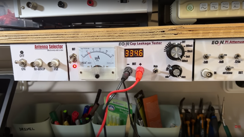
We like [Manuel]’s construction method here, with custom PCBs nestled inside a simple bent aluminium enclosure. No need for a top or sides, as these, are intended to bolt underneath a shelf, and butt up against their neighbor. The front panel graphics are done in a simple but very effective manner, using printable sticker sheets, with a clear adhesive over-sheet. They certainly have a professional finish, and this is definitely a construction method worth considering.
For those a little unfamiliar with this important component, why not leap into some theory with this handy dive into the simple parallel plate capacitor? Next, may we suggest a little overview of the different capacitor types and how to best make use of them?


I would have opened the meter and obscured the movement info (“µA”, etc).
Why? That’s exactly what it is displaying!
As a user, you read it according to the Leakage switch scale. The actual internal current driving the meter is no longer important once it’s completed and tested.
It’s an ammeter. It reads microamps. Just like it’s labeled. When the switch is set to the most sensitive (x1) position, it’s 100 uA full scale, just like it says. The remaining switch positions are x10, x100, x1000 multipliers, but it’s still microamps.
Should it read just generic ‘Current’ instead of ‘uA’?
Should the scale also be relabeled to ‘1.00’ full scale? Or no numbers at all? Or do you think it should be called ‘percent’?
Great project!
It looks to me that it should be left a little longer in 100mA range for the higher capacity capacitors, so to have more time to fast charge (and to measure the actual leakage without the influence of charge current).
I went through his videos to see how he did the panel labeling. Was simultaneously gratified and sad to see it’s exactly the same process I’ve been doing since 1997. Still can’t find a faster/easier/cheaper/better way for one-ofs, but it’s still annoyingly fiddly.
Used to use inkjet, then colour laser, now dye-sub. Used to use Avery cover material, which is pretty soft, but now use Hashi laminate (hashimall.com), which is much harder, doesn’t wrinkle when you snug a nut up on it.
Label font on the left side panel is good, the rest are hard to read. Curved text is even worse. The meter’s native rating in not needed either, the 4 ranges apply only.