[Chris Jones] recently found himself in a pickle. An indicator LED off an old piece of stereo equipment had failed. It was a strange rectangular type for which he could source no modern substitute. Using a different LED would ruin the aesthetic. Thus, what else was [Chris] to do, but attempt surgery on an LED!
The first attempt was the simplest. [Chris] tried soldering a small SMD LED between the legs of the existing part, which was open circuit. It worked, but the light didn’t really propagate to the top of the LED’s plastic. It was too dim to do the job.
Unperturbed, [Chris] instead elected to cut the LED apart. he soldered the SMD LED to the original LED’s leads, inside its body this time. The top part of the plastic lens was then notched to fit snugly over the new SMD part. A bit of superglue then joined everything back together. The finished product looks a touch messy on the PCB. However, installed back inside the stereo, it’s a perfectly stealth fix that looks great.
Some will consider this fix frivolous and a waste of time. Others will appreciate the way it preserved the attractive retro look of a piece of vintage audio gear. In any case, we can all agree that modern LEDs are often a great replacement for older parts in many cases. If you’ve pulled off your own weird, oddball repair hacks, don’t hesitate to share us with them on the tipsline!
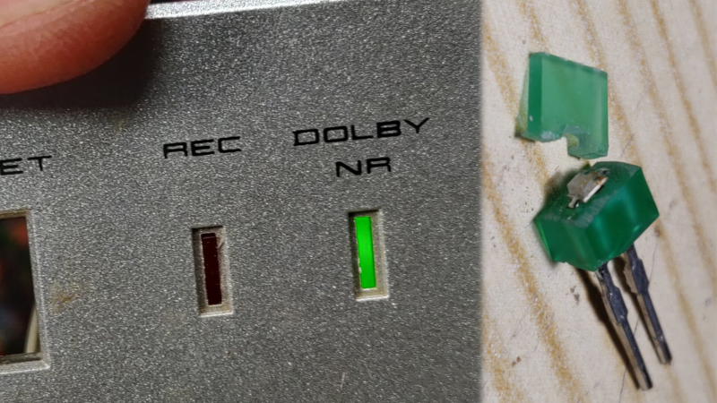
This green LED has stopped working. I think it's my fault – one leg shorted to the chassis while it was switched on and gave it 15V which it didn't like. It's an odd shape so we can't buy a new one. Can we fix it? 🧵 /1 pic.twitter.com/DX71Kk0TP5
— Chris Jones (@mjtech01) January 25, 2023


One thing to note is that modern LEDs are substantially brighter and may become overdriven when substituted for old LEDs in circuit. You no longer need to use 25 mA to drive a red LED.
Thanks gramps.
Also worth a look, err, a watch:
https://m.youtube.com/watch?v=yusrrOPM43o
Just making a note for all the electronics designers who think that the indicator lights on appliances should light up the entire damn room at night.
I second your sentiment. In some cases, they have kept me from sleeping soundly as the light is unnatural and in total darkness becomes a beacon.
More than one of my TV’s round the home have a red LED when off and a blue LED when on.
Why?
Why do we need a LED tobe on when the TV is on? The picture is on the screen or else the moving message saying no input surely will do ?
All the on LED does is distract you from the picture, waste energy and cost to put it on the pcb.
Dude pointed out that many modern engineers are designing things with far too much current and there for brightness now.
Half my bedroom glows when I’m trying to sleep because of a fire alarm.
Dude’s observation is valid and his technical explanation is correct.
This “Thanks gramps” seems very much like the “OK boomer” attitude.
Us “gramps” did very well and we worked with older people who enriched out knowledge and experience.
We did well then and today as all work as a team irrespective of age.
I certainly wouldn’t want you on my team. Keep that in mind on your next job interview.
Amen
heh and on top of that i have had a dickens of a time finding proper specs for a lot of LEDs, even when i go to specialty LED vendor websites. i kept using a certain LED, the website called it a 100mA LED, and i was way under-driving it at 20mA, and it was suffering all manner of failure modes. i finally dug around and found a little more information on it, turns out it was rated for 20mA and they copied the “peak instantaneous for PWM” current value to find 100mA.
on top of that, it wasn’t that durable at 20mA either, though maybe that was my fault somehow — i didn’t realize i was bumping right up against the limit. and on top of *that*, even with modern “ultrabright” LEDs, the red ones sometimes draw a lot more than the white ones to get to a similar level of brightness. but i assume some of the red ones are just white ones with a colored filter on them.
so it’s really exasperating that documentation is so hard to come by for such a cheap and common component sometimes, now that there are so many details to know.
though for an indicator LED at least you won’t be sitting there with your bench supply trying to find the “sweet spot” of how bright you can get it without an undue drain on your battery!
Red LEDs are not white LEDs with a filter. That would be an extraordinarily stupid way to make a red LED.
If you need data on your LEDs, the secret is to buy the LEDs from a reputable dealer. Amazon, eBay, and Alibaba are NOT reputable dealers. Check out Digikey, Mouser, or RS.
Yes. White LEDs came after red, green, orange and blue. It seemed like a long time when we were waiting.
whites are really just blues with a phosphor layer.
Blue LEDs were also a long time coming. IIRC the guy who figured it out was trying to make a side firing solid state blue LASER, but the dies kept cracking. Then he noticed the cracks *glowed blue*. So he shifted his work to making the dies crack even more.
But that work was built on when he had previously worked for RCA, where the first blue LEDs were made in 1972. RCA abandoned their LED work when David Sarnoff died and his son took over, then killed off several R&D projects as part of his budget slashing schemes. He and two other guys who worked on developing and commercializing blue LEDs got a Nobel Prize in physics, but the man who really invented the first blue LED at RCA got nothing.
I wasn’t waiting, I was using miniature incandescent lamps for my hobby projects. ^^
They were very modern for their time, too, I think. They were bi and liked AC/DC!
maybe there has been recent progress in red LEDs?
i have a bucket of cheapo white LEDs that are *much* brighter at 5mA than expensive “ultrabright” red LEDs at 20mA. i know what you’re saying about the history of red LEDs coming decades before the blue LEDs. and i have no idea what the spread of products is that is available from different vendors if you really go digging.
but i’m gonna stand firm on this: it would absolutely not be extraordinarily stupid to put a red filter or phosphor/scintilator on a blue/white LED. the blue LED technology is just so fantastically more energy efficient than the older red LED technology.
Red LEDs are getting close to the theoretical maximum perceived brightness for that color of light.
Given that white LEDs are mostly [b]yellow[/b], adding a red filter on top would be a great way to bring the efficiency down to 1970s red LED levels.
There are some COB LED boards that use phosphor converted colors like that to keep the forward voltage and current limiting resistor the same,as well as the PCB series/parallel setup.
Specifically look at emergency strobe lighting for some common examples
>Red LEDs are not white LEDs with a filter. That would be an extraordinarily stupid way to make a red LED.
What if you have buckets and buckets of off-spec “white” diodes rejected by a customer and someone asks for red indicator LEDs?
Sell the buckets of reject white LEDs back on Amazon where you got them. Do the right thing for your customer and give them red LEDs.
Then you ignore the random online comments, solve the problem the way you see fit, and get on with your life.
I own several million “red LEDs” which are white LEDs with a filter. I also have several million green and blue ones built the same way.
This is how many OLED screens from LG are constructed. It provides a level of consistency in drive brightness levels and aging dimming, which would be hard to manage with the distinct voltage and power requirements of the color-by-band-gap LEDs.
It is not a stupid way – it’s a different way. Matching the technology to the requirements is not stupid.
you can still get indicator leds rather than super brights. just not these old style rectangular ones, but that seems like a simple exercise in resin casting.
Great hack. But his looks like a 5xSomething mm LED. 5x2mm can still be found, maybe grinding a 5x2mm would have been easyer
Get round 3mm or 5mm LED (depending how tall the opening is). File both sides so it fits the square opening. Optionally file the front, so it is flat. Much simpler.
Or, y’know, just buy a rectangular LED and file it to fit. There are thousands of them out there, just not the exact same shape as that particular one.
Just fill the hole in panel with hot glue and put whatever LED you have behind it.
Visiting Akihabara in the mid-late 70s I picked up a few unusual shape LEDs such as rectangular ones much like the one shown here and also triangular ones. I still have them somewhere
I have some old rectangular LED’s in my parts stash – red, green, AND yellow. Fortunately, (or unfortunately), I didn’t have to go to Japan to get them. I picked them up in Toronto somewhere, back when we were blessed with LOTS of retail electronics component suppliers. IIRC I even have at least one triangular LED. Yup, just call me Gramps…
You’ve kept your unusual shape LEDs for approaching 50 years? I’m a hoarder too… you’re really prompting me get some will power and chuck some stuff out.
For real ? I had held a few of them in my hands, already. I had no idea they’re threatened with extinction.
I always thought they were still commonly used in the hi-fi/tuner sector.
Why aren’t they noloner, by the way ? Their aesthethics aren’t bad, after all!
It’s light pipes that go to surface mounted LEDs these days. Much more durable during assembly of the equipment.
Microsoft’s Optical Trackball One (the thumb version) suffered a terrible out of box failure rate because of the red tracking LED. Uncareful assemblers could hit the LED hard enough to break one of its solder connections so it wouldn’t light. Unfortunately those trackballs were made in the early “gee whizz” era of optical input devices so they also had a second red LED that did nothing but light up the transparent red ball socket to say “Look, I’m optical!”. So when the people at the factory would plug them in to test, they’d see *a* red light and assume they were good then send them off to packaging. The illumination LED was quite a bit dimmer than the tracking LED, but apparently the testers weren’t advised of that fact.
A HUGE number of those pre-broken trackballs ended up for sale on eBay and the fix was a quick hit with a soldering iron.
Unfortunately, Microsoft chose to use soft steel bearing balls in the ball sockets on both models of their optical trackball instead of silicon carbide *like every other trackball*. One must keep a fastidiously clean thumb or fingers and religiously clean any fuzz and other buildup or the steel balls will wear down and the big ball will drag against the socket. There were people charging pretty good $ to somehow replace the steel balls with silicon carbide to revive the trackballs and ensure trouble free use for a long time.
Thank you very much for the background information! 😎👍
They look like LEDs I got from Radio Shack in the 1990s. Might still have a few.
I think I have couple of those led type, If you wish I can search for them and send to you…
Been there done that, just didn’t document it.
The type of stereo device was the same exact (cassette deck), but it had LED level indicators. These were comprised of very unusual package-of-three rectangular LEDs. One was dead which caused the IC driving them to miss an entire segment of four, which not only looks unpleasing, but won’t allow you to set your recording levels (yes I’m one of the few remaining lost cases that still record on tape). I drilled out the old LED from the bottom and then there was enough space for a round 3mm LED under it. These LEDs had factory tolerances so bad you couldn’t see which one of them I replaced (hint: It was the second most bright one).
Btw. in the 90s young me who liked LEDs bought a bag with mixed LEDs (red, green, yellow, no blue back then) and they have this form factor, so I have lots of those.
Btw². from the styling I’d say the tapedeck involved is an Akai early 80s. I had a CS-M01 for over a decade.
Actually, these square shape leds, you still can get it from i.e. aliexpress :
https://www.aliexpress.com/item/32853087616.html
No. Those LEDs on aliexpress are just a rectangle.
I think I remember LEDs like these. They were in already-old equipment I tore apart as a kid. They are a larger rectangle on bottom with a smaller rectangle on top that sticks out the top. On it’s side it might be shaped either like a two-step staircase or two of them back to back. Another variation, instead if being a true rectangle sticking out the top has one that is tapered.
I am surprised these can’t be found. I wonder if it’s just a matter of knowing what that style is called in order to be able to enter the right search term.
That said, once assembled you only see the top edge so I suppose a plain rectangle would be fine if it’s dimensions are right.
First off, I love the idea of opening up the LED to replace the die. That’s hilarious. I now think of SMT LEDs as being like replacement lightbulbs for 5 mm LEDs.
Second, rectangular LEDs are the best. I did a microcontroller trainer board, and wanted to display the pin state of a whole byte. These LEDs are just under 0.1″ (2.5 mm) thick, so they fit super nicely on a standard DIP grid raster and look great.
Yeah, I built a few of those, buffered and unbuffered, when I first started playing with microcontrollers, turned out to be really handy for fault finding on home computers and PCs too.
Saves a lot of effort when you realise bargraph LED modules exist with 0.1″ pitch 16 DIL package though.
I’m suprised that they couldn’t be found at Mouser or Digikey. I’ve found some weird LEDs there, most recently some hi-brightness oval LEDs with horizontal only viewing angle specifically made for scoreboards. I’ve come across a lot of rectangular LEDs over the years and salvaged a lot of them. Maybe HAD needs a parts exchange board?
You don’t have to drive LED’s at their maximum current rating. I’m convinced that all of the Edison LED bulbs I’ve ever bough that have subsequently failed (a lot of them) were because they tried to drive the LEDs at max current.
a few mA down and they last forever with no human noticeable difference in brightness
Well how else are you going to get that “60 Watt equivalent” Lumen rating out of a 6 Watt lamp?
The industry standard way to measure the luminous output at the nominal power is at 25 C junction temperature. That means the LED is briefly pulsed on for like 10 milliseconds to measure the light output.
Then you’re supposed to de-rate for the actual operating temperature etc. but do you think the cheap manufacturers bother? If the datasheet says this is a 6 Watt diode, they will run it at 6 Watts sharp and print the datasheet lumen number on the box. The actual lamp will dim by 30% in a matter of seconds after you turn it on, and cooks up in about a year. That sells another lamp.
On top of that, they use LED modules with high voltage drop (around 9v usually, i guess each LED module has three discrete ones inside but they don’t look like it at all) and wire them up in series, in order to use a very low current, high voltage power supply. or a capacitor in series as ballast, in worse cases. You end up with as many as 20-something LEDs in series, driven at their maximum capacity, inside an airtight enclosure. Yet nobody with political power seems to care, because making them more durable like LED strips means more cost and way less demand.
What I’ve done in the past is go dremel-tastic on a larger LED and shave it down to the dimensions I need. Hit the top viewing surface with some 1200 grit and give it a nice smooth finish and it looks original.
Im not sure what the issue was, found them first search on mouser
LUMEX seems to be still making 5x2mm Indicator LEDs
I’m with the guys recommending to file the LED into shape. Works a treat, have done it dozens of times. The surface is easily polished too. What this guy did is in my opinion just unnecessarily complicated and labour intensive. Filing takes around 5 minutes or less.
Username checks out.
Why not just use a Kingbright L-113IDT? They are generally available.
Fixing it in place spares you the search, of course, and you get the result *now*.
Sorry, “Kingbright L-113GDT” is the green variant (5×2 mm). Additionally, there are 5×2.4 mm and 5×2.5 mm LEDs available from Kingbright and Everlight, at least.
Panasonic LN324GP seems to be the correct shape
https://www.digikey.com/en/products/detail/panasonic-electronic-components/LN324GP/10506?s=N4IgTCBcDaIA4GYCMA2AtAOwCYgLoF8g
Shoulda asked me, I have a whole bag of them. Somewhere.
Neat solution. I’ve seen quite some odd shaped LEDs through the years. I used to have a few different sizes, as well as a few pieces of colored acrylic for that job.
All you need is a strip of colored acrylic, a file, perhaps a small hacksaw, and a lighter to polish the surface.
Oh, and cyanoacrylate. But of course, we hackadayers buy that in bulk (and a sensible one buys it in bulk with a bottle of acetone, for safety) 😉