Antennas are a key component to any RF gadget. But antennas often only perform well over a narrow band of frequencies. For some applications, this is acceptable, but often you would like to reconfigure an antenna for different bands. Researchers at Penn State say they’ve developed a tunable antenna using compliant mechanisms and electromagnets. The new scalable design could work in small areas to provide frequency agility or beamforming.
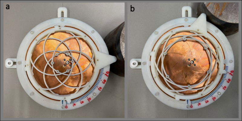
The prototype is a circular patch antenna made with 3D printing. If you want to read the actual paper, you can find it on Nature Communications.
A compliant mechanism is one that achieves force and motion through elastic body deformation. Think of a binder clip. There’s no hinge or bearing. Yet the part moves in a useful way, using its own deformation to open up or grip papers tightly. That’s an example of a compliant mechanism. This isn’t a new idea — the bow and arrow are another example. However, because 3D printing offers many opportunities to build and refine devices like this, interest in them have increased in recent years.
We couldn’t help but notice that the antenna is a variation of a “compliant iris” like the one in the video below. You can find designs for these online for 3D printing, so if you wanted to experiment, you might think about starting there.
We’ve looked at compliant mechanisms before. Why would you want better chip-scale antennas? Why, indeed.


Looks like you need to adjust by hand.
Impractical but could they have hooked up a servo and a VNA to tune in the fly?
Exercise left up to the reader
You wouldn’t want to tune in a fly, I suspect the limitations on antenna size would be problematic.
No that’s a video of the system without actuator
CP antennae don’t really have a “beam” or “significant direction” in their radiation patterns according to the white papers I have read, and are more “iso” than almost every other type of antenna as far as I can tell – the most prominent lobe I have seen is a 3dB gain perpendicular to the plane, achieved with cutouts of certain sizes and orientation. That’s not a lot in the frequencies and applications necessitating an antenna of this design.
Are these researchers doing something different or using external elements to achieve this directionality? (not referring to the frequency agility tuning)
I’m unsure what you mean by “CP” in this context. Usually iot refers to circular polarization, but the polarization makes no distinction about gain or radiation pattern.
Skimming the text on the linked article tells us that their initial desire was to make this:
“The target goals were to achieve a high-gain conical or monopole-type radiation pattern for a frequency regime that exceeds current state-of-the-art all-electronic solutions, while offering other performance advantages such as structural robustness and actuation simplicity.”
The monopole antenna was definitely directional.
It was measured to have these gains on these frequencies:
” Realized gain in the three cases presented are 6.1 dBi at 3.46 GHz, 7.6 dBi at 4.46 GHz, and 7.4 dBi at 6.18 GHz. Maximum realized gain of 10.8 dB is achieved at 3.82 GHz, but as demonstrated in Fig. 9a realized gain doesn’t drop below 6 dBi until 6.62 GHz.”
Even gain towards horizon is gain instead of pure isotropic radiator.
This is the article I’m quatoing from:
https://www.nature.com/articles/s41467-023-36143-6
“Circular Patch” antenna, as stated in this article.
The video is not the proposed invention but a step toward it. Obviously a electromagnet or rather 2 work to compress the antenna section and change the shape, a resistive means and diode could be used to auto tune the system with little input on the relay leads… Or not I’m just curious
Okay so 2 more options for this wave form system.
Layers in a sheet form larger or smaller Yagi sections or woven material metallic and non metallic strings make contact with each other to form larger sections
It may be easier to use several sheets of antenna with shape being changed by mobile magnetic waves forcing the antenna sections apart