Flexures Make Robotic Fingers Simpler To Print

Designing an anthropomorphic robotic hand seems to make a lot of sense — right up until the point that you realize just how complex the human hand is. What works well in bone and sinew often doesn’t translate well to servos and sensors, and even building a single mechanical finger can require dozens of parts.

Or, if you’re as clever about things as [Adrian Perez] is, only one part. His print-in-place robotic finger, adorably dubbed “Fingie,” is a huge step toward simplifying anthropomorphic manipulators. Fingie is printed in PLA and uses flexures for the three main joints of the finger, each of which consists of two separate and opposed coil springs. The flexures allow the phalanges to bend relative to each other in response to the motion of three separate tendons that extend through a channel on the palmar aspect of the finger, very much like the real thing.

The flexures eliminate the need for bearings at each joint and greatly decrease the complexity of the finger, but the model isn’t perfect. As [Adrian] points out, the off-center attachment for the tendons makes the finger tend to curl when the joints are in flexion, which isn’t how real fingers work. That should be a pretty easy fix, though. And while we appreciate the “one and done” nature of this print, we’d almost like to see the strap-like print-in-place tendons replaced with pieces of PLA filament added as a post-processing step, to make the finger more compact and perhaps easier to control.

Despite the shortcomings, and keeping in mind that this is clearly a proof of concept, we really like where [Adrian] is going with this, and we’re looking forward to seeing a hand with five Fingies, or four Fingies and a Thumbie. It stands to be vastly simpler than something like [Will Cogley]’s biomimetic hand, which while an absolute masterpiece of design, is pretty daunting for most of us to reproduce.

Continue reading “Flexures Make Robotic Fingers Simpler To Print”

Flexures Keep This Printed Displacement Sensor In Line

When the job at hand is measuring something with micron-range precision, thoughts generally turn to a tool with a Mitutoyo or Starrett nameplate. But with a clever design and a little electronics know-how, it turns out you can 3D print a displacement sensor for measuring in the micron range for only about $10.

While the tool that [BubsBuilds] came up with isn’t as compact as a dial indicator and probably won’t win any industrial design awards, that doesn’t detract from its usefulness. And unlike a dial indicator — at least the analog type — this sensor outputs an easily digitized signal. That comes courtesy of a simple opto-interrupter sensor, which measures the position of a fine blade within its field of view. The blade is attached to a flexure that constrains its movement to a single plane; the other end of the flexure has a steel ball acting as a stylus. In use, any displacement of the stylus results in more or less light being received by the phototransistor in the opto-interrupter; the greater the deflection, the less light and the lower the current through the transistor. In addition to the sensor itself, [Bub] printed a calibration jig that allows precision gauge blocks or simple feeler gauges to be inserted in front of the stylus. The voltage across the emitter resistor for these known displacements is then used to create a calibration curve.

[Bub] says he’s getting 5-micron repeatability with careful calibration and multiple measurements of each gauge block, which seems pretty impressive to us. If you don’t need the digital output, this compliant mechanism dial indicator might be helpful too. Continue reading “Flexures Keep This Printed Displacement Sensor In Line”

Pushing The Boundaries Of Tiny Mechanical Devices With Compliant Mechanisms

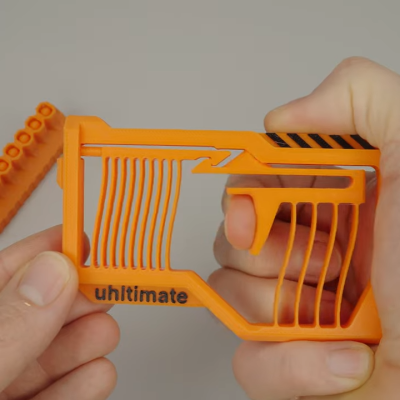
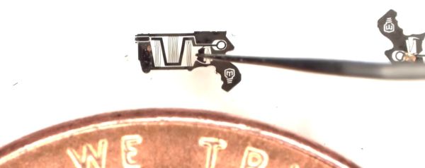
Mechanical actions underlie much of what makes modern day society function, whether it’s electric motors, combustion engines, switches, levers, or the springs inside a toy blaster gun that propel foam darts at unsuspecting siblings. Yet as useful as it would be to scale such mechanisms down to microscopic levels, this comes with previously minor issues on a macroscopic scale, such as friction and mechanical strength, becoming quickly insurmountable. Or to put in more simple terms, how to make a functioning toy blaster gun small enough to be handled by ants? This is the topic which [Mark Rober] explores in a recent video.

Continue reading “Pushing The Boundaries Of Tiny Mechanical Devices With Compliant Mechanisms”

Physical Neural Network Can Be Trained Like A Digital One

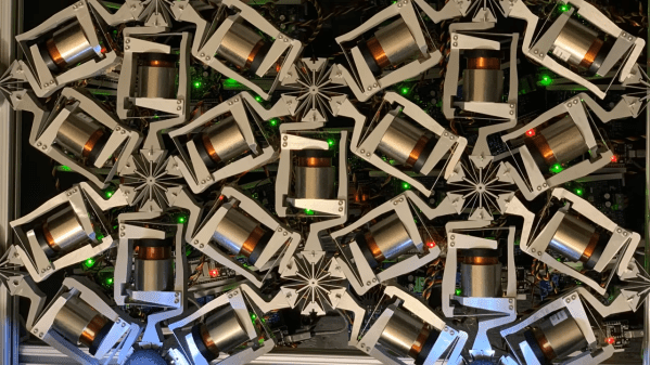
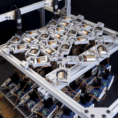
Here’s an unusual concept: a computer-guided mechanical neural network (video, embedded below.) Why would one want a mechanical neural network? It’s essentially a tool to explore what it would take to make physical materials work in nonstandard ways. The main part is a lattice of interlinked mechanical components. When one applies a certain force in a certain direction on one end, it causes the lattice to deform in a non-intuitive way on the other end.

To make this happen, individual mechanical elements  in the lattice need to have their compliance carefully tuned under the guidance of a computer system. The mechanisms shown can be adjusted on demand while force is applied and cameras monitor the results.

This feedback loop allows researchers to use the same techniques for training neural networks that are used in machine learning applications. Ultimately, a lattice can be configured in such a way that when side A is pressed like this, side B moves like that.

We’ve seen compliant structures that move in unexpected ways before, and they are always fascinating. One example is this 3D-printed door latch that translates a twisting motion into a linear one. Research into physical neural networks seems like it might open the door to more complex systems, or provide insights into metamaterial design.

You can watch the video below just under the page break, or if you prefer, skip the intro and jump straight into How It Works at [2:32].

Continue reading “Physical Neural Network Can Be Trained Like A Digital One”

Electromagnetic Mechanism Makes Reconfigurable Antenna

Antennas are a key component to any RF gadget. But antennas often only perform well over a narrow band of frequencies. For some applications, this is acceptable, but often you would like to reconfigure an antenna for different bands. Researchers at Penn State say they’ve developed a tunable antenna using compliant mechanisms and electromagnets. The new scalable design could work in small areas to provide frequency agility or beamforming.

The prototype is a circular patch antenna made with 3D printing. If you want to read the actual paper, you can find it on Nature Communications.

A compliant mechanism is one that achieves force and motion through elastic body deformation. Think of a binder clip. There’s no hinge or bearing. Yet the part moves in a useful way, using its own deformation to open up or grip papers tightly. That’s an example of a compliant mechanism. This isn’t a new idea — the bow and arrow are another example. However, because 3D printing offers many opportunities to build and refine devices like this, interest in them have increased in recent years.

We couldn’t help but notice that the antenna is a variation of a “compliant iris” like the one in the video below. You can find designs for these online for 3D printing, so if you wanted to experiment,  you might think about starting there.

We’ve looked at compliant mechanisms before. Why would you want better chip-scale antennas? Why, indeed.

Continue reading “Electromagnetic Mechanism Makes Reconfigurable Antenna”

Flexures Make This Six-DOF Positioner Accurate To The Micron Level

It’s no secret that we think flexures are pretty cool, and we’ve featured a number of projects that leverage these compliant mechanisms to great effect. But when we saw flexures used in a six-DOF positioner with micron accuracy, we just had to dig a little deeper.

The device is known as the Hexblade, and it comes to us from the lab of [Jonathan Hopkins] at UCLA. We have to admit that at times, the video below feels a little like the “Turbo Encabulator” schtick — “three identical decoupled actuation limbs arranged in an axisymmetric configuration” may be perfectly descriptive, but it does not flow trippingly from the tongue. Hats off to [Professor Hopkins] for nailing the narration, though, and really, once you get a handle on the jargon, it all makes perfect sense. The platform is supported by a total of six flexures, which look like bent pieces of sheet metal but are actually cut from a solid block of material using wire EDM. Three of the flexures are oriented in the plane of the platform, while the other three are perpendicular to it. The far end of each flexure is connected to a voice-coil actuator that is surrounded by another flexure, this one in a parallelogram arrangement. The six actuators can move the platform smoothly through three linear translations (X, Y, and Z) and three rotations (roll, pitch, and yaw).
The platform’s range of motion is limited, but the advantages of using flexures as bearings are clear — there’s no backlash or hysteresis, and the voice coils can control the position of the stage to micron accuracy. Something like the Hexblade would be an ideal positioner for microscopy, and we can imagine an even smaller version, perhaps even a MEMS-fabricated one for nanomanufacturing applications. The original concept of the Hexblade serving as the print head for a fabrication robot for space applications is pretty cool, too, and we’d venture to say that a homebrew version of this probably isn’t out of reach either.

Continue reading “Flexures Make This Six-DOF Positioner Accurate To The Micron Level”

A MetaSense joystick

3D-Printing Complex Sensors And Controls With Metamaterials

If you’ve got a mechatronic project in mind, a 3D printer can be a big help. Gears, levers, adapters, enclosures — if you can dream it up, a 3D printer can probably churn out a useful part for you. But what about more complicated parts, like sensors and user-input devices? Surely you’ll always be stuck buying stuff like that from a commercial supplier. Right?

Maybe not, if a new 3D-printed metamaterial method out of MIT gets any traction. The project is called “MetaSense” and seeks to make 3D-printed compliant structures that have built-in elements to sense their deformation. According to [Cedric Honnet], MetaSense structures are based on a grid of shear cells, printed from flexible filament. Some of the shear cells are simply structural, but some have opposing walls printed from a conductive filament material. These form a capacitor whose value changes as the distance between the plates and their orientation to each other change when the structure is deformed.

The video below shows some simple examples of monolithic MetaSense structures, like switches, accelerometers, and even a complete joystick, all printed with a multimaterial printer. Designing these structures is made easier by software that the MetaSense team developed which models the deformation of a structure and automatically selects the best location for conductive cells to be added. The full documentation for the project has some interesting future directions, including monolithic printed actuators.

Continue reading “3D-Printing Complex Sensors And Controls With Metamaterials”