HF radios often use toroidal transformers and winding them is a rite of passage for many RF hackers. [David Casler, KE0OG] received a question about how they work and answered it in a recent video that you can see below.
Understanding how a conventional transformer works is reasonably simple, but toroids often seem mysterious because the thing that makes them beneficial is also what makes them confusing. The magnetic field for such a transformer is almost totally inside the “doughnut,” which means there is little interaction with the rest of the circuit, and the transformer can be very efficient.
The toroid itself is made of special material. They are usually formed from powdered iron oxide mixed with other metals such as cobalt, copper, nickel, manganese, and zinc bound with some sort of non-conducting binder like an epoxy. Ferrite cores have relatively low permeability, low saturation flux density, and low Curie temperature. The powder also reduces the generation of eddy currents, a source of loss in transformers. Their biggest advantage is their high electrical resistivity, which helps reduce the generation of eddy currents.
If you haven’t worked through how these common little transformers work, [David]’s talk should help you get a grip on them. These aren’t just for RF. You sometimes see them in power supplies that need to be efficient, too. If you are too lazy to wind your own, there’s always help.


I’ve been working on designing a chunk of magnetic core memory, which uses quite different-material toroids, but one thing I ran across that was kinda cool was how IBM managed to design magnetic core memory that only needed unidirectional drivers to write/read the core array, which they did by very clever use of conventional ferrite cores as both amplifiers and logic gates. The same sort of process that lets you selectively write magnetic core memory, where you have two wires passing through the core that both have to be energized to exceed the core’s threshold of magnetization, also lets you use the cores as AND gates, and without a lot of work you can also get a core to work as a NOT, and at that point, you have the building blocks for as much digital logic as you want.
This was a really bad video. It didn’t explain anything, he just went “Becuase of Maxwell”.
Well, why does it work like that?
Well, as far as that goes, Maxwell didn’t explain WHY a changing magnetic field induced current (and vice-versa) in a conductor, either. What he developed were the four equations that relate electricity and magnetism, as Casler explains. But Casler throws so much other crap in there, including perpendicular E and B field vectors in space, using the wrong terminology at least twice, it just muddies the whole subject, and doesn’t contribute to the explanation at all.
What is in play in an inductor or transformer is Faraday’s law (which is one of Maxwell’s laws), which states that “the work per unit charge required to move a charge around a closed loop equals the rate of change of the magnetic flux through the enclosed surface,” which is how Oliver Heaviside summarized Maxwell’s cryptic equations. The “enclosed surface” here is a single loop of the wire, and it is the changing magnetic flux through this (through the toroid’s core, that is,) that induces this current (the moving charge). Many textbooks and instructors teach a bastardized version of this that has something to do with “cutting” lines of flux, which is utter nonsense and just leads to questions like “but what about toroids?”
This is a little like the nonsense explanations of how a wing generates lift that were taught to generations of aviators, who after all don’t really need to understand aerodynamics well enough to design an efficient wing, but just enough to remember that when you pull back on the yoke, the tail goes down and the plane goes up, and that exceeding a certain angle of attack will make your wing stop lifting. I just read yesterday that Einstein (yes, that Einstein (thanks for that phrase, Sabine Hossenfelder)) once designed an airplane wing, but it was a failure because he was basing his design on faulty explanations of lift that HE was taught!
Agreed. It was pretty much pointless, it missed some important information, and it was misleading.
First, EMF stands for Electro-Motive Force, not Electro Magnetic Field.
Second, not all toroidal cores are ferrite. Some – even for RF work – are powdered iron. And at lower frequencies, such as in mains transformers, toroidal cores can be soft iron like that used in E-core designs.
Third, it’s important to know that in a turns-ratio sense, there’s no such thing as a fractional turn in a toroidal inductor or transformer. As soon as the wire exits one end of the aperture, a turn has been added. Even when that wire has been wrapped around again to the point where it’s just about to re-enter the aperture at the other end, there has still only been one turn added – not one-and-a-half turns, or one-point nine turns, or whatever. Only when the wire is pulled through again does the turns count increase. In RF work, fractional turns may alter the behaviour of a toroidal transformer because of things like capacitance, leakage inductance, coupling, so it may LOOK like you have a fractional turns ratio – but you really don’t.
I seem to remember that for wire in a toroid without an actual core, there are definitely half turns. But (and I haven’t done the math to confirm it) I’ve had it suggested that for high enough permeability of a toroidal core, the parts of the wire on the outside edge are somehow irrelevant, and it’s only the passes thru the center which contribute. Do you have a good explanation or source for an explanation of how that could be true? And if so, then why wouldn’t it mean interesting things about the voltage distribution or something?
From a source I mentioned in a reply a bit farther down, I take it that a toroidal core concentrates most of its flux in the centre. The wire outside the aperture is exposed to magnetic flux, but at much lower levels.
Regarding the voltage distribution, that’s a really interesting question. I don’t know the answer, but my spidey sense tells me that a clue may lie somewhere in this seemingly off-topic video:
https://www.youtube.com/watch?v=0TTEFF0D8SA
I find the guy annoying, but he really knows his stuff. And if I’m wrong about it addressing your voltage distribution question, it’s at least interesting and informative.
And also this video, the conclusion to the one I linked above:
https://www.youtube.com/watch?v=Q9LuVBfwvzA
The videos were nice and answered some probing questions :D. The thing that makes me more confident about this is having played with an inductance meter with a thin EE ferrite core pair for a few minutes. I didn’t probe to find out everything, but I think the closed geometry is representative of a toroid too.
And a story I can tell myself is that for the section of wire through the center, looking radially out at the surroundings the average permeability is very high, so the twist of the magnetic field by its current is applied to the core all the way around the wire. But on the outside, the only direction where its effect goes through something highly permeable is in the side towards the core. Even if the wire extends axially an infinite distance, it still makes sense for the swirl to be stronger when it’s coaxial with the core rather than parallel but outside, as the components would still add up better.
So, for a flat enough core with a high enough permeability, the majority of the effect would occur in a really small distance. If people have become convinced by their measurements that only integer turns can exist, I would expect that to be right. Guess the voltage distribution is uneven, but maybe it’s not that big of a deal usually.
So imagine you have a coil, and for arguments sake, it has 36 of the imaginary field lines we like to draw.
Now if it is a solenoid, those 36 lines go up the middle, and then loop back down the outside to get to the bottom, spaced 10 degrees apart.
You can easily wind a coil with a 1/2 turn that is only looped by 18 of the field lines, and then exits through the other 18, to escape the field lines.
But in a toroidal coil, the field lines go around the core, back to the start without exiting the toroid. Any turn, forms a full loop – because the rest of the circuit, i.e. all the wires connected to your transformer and completely outside the core are part of teh turn too. As long as you consider the whole entireity of the current flow, you realise that is must always form a complete loop around the core, regardless of where the copper wire ends, and the pcb track etc begins.
Fair enough. But if you give the loops of wire around a solenoid core a diameter much larger than the core itself, you can expect the inductance to decrease a lot. If you do the same with a toroidal core, I don’t think the inductance decreases to any great extent. I could be wrong about that though. In either case, the Q will certainly decrease.
“fractional turns” totally exist if you think in proportions of (rate of change of) magnetic flux density seen by the windings. They even have some use: https://ieeexplore.ieee.org/document/9487397
That’s a bit over my head I’m afraid. If I’m incorrect, and fractional turns on a toroid do contribute to flux and coupling, do they contribute to the same degree as the parts inside the aperture? Or does a half-turn – in the topological sense – contribute much less than half of a full turn?
I don’t have access to the entire IEEE article, but what I can see shows planar transformers, which seem to have a magnetic circuit similar to that of traditional two-aperture E-I cores. I would guess that in this case a half-turn can exist, because there are two apertures and therefore two magnetic circuits as opposed to a single circuit in a toroid core. I’m not clear on smaller fractions of a turn though.
After my post a few minutes ago, I found this:
https://maker.pro/forums/threads/core-imbalance-in-rcds.28112/page-2
This doesn’t seem to be an authoritative source, but it confirms my last speculation:
“Toroids are just a special case, which cannot change the basic laws of
physics, and cannot change the fact that partial turns give different
voltages, but the partial turns have much less effect in a toroid transformer,
because the effect is masked by the strong effect of going through the
core or not.”
That suggests that the wire outside the aperture encounters some flux, but that the flux on the outside of the toroid is dwarfed by that inside the aperture, causing even large-fraction partial turns to contribute much less to coupling than complete turns.
What I was expecting was some take on the idea of, well, if you have a magnetic flux going right here then why does a copper wire over there experience EMF? Saying “Maxwell” is just repeating a dogma – it’s describing the phenomenon but not explaining why.
https://en.wikipedia.org/wiki/Nominal_fallacy
Describing phenomena is what science DOES. When we do this, that happens. Every time, if you’re doing good science. I had a chemistry professor who, whenever asked “why” anything worked the way it does, always answered, “because God made it that way.” Which annoyed many of his students, but his point was that “why” does not belong in a proper scientific question.
What?!
Science or more specific “the scientific method” is (kinda)
1. observing and describing a phenomena (+ quantify it?).
2. thinking up a falsifiable theory which explains(!) it (=explaining why!).
3. derive predictable changes/reactions.
4. test that theory (if 3. actually works).
rinse and repeat
-> https://commons.wikimedia.org/wiki/Category:Scientific_method
Science is all about the why.
Your chemistry prof was either lazy or I don’t know. Just look at the evolution of atomic models from https://en.wikipedia.org/wiki/Atomic_theory#Discovery_of_subatomic_particles (Plum pudding model) over https://en.wikipedia.org/wiki/Bohr_model to https://en.wikipedia.org/wiki/Atomic_orbital
“Why do H and O2 burn and react into H2O?” “Because god made it that way.” What again?!
The professor was totally right. Science is the way to see which math describes which effect in physics. You can ask why the math works this way, but not why the math describes this or that correctly. It is like you have the construction instructions of a bridge, you can exactly say how to build a bridge, and how far and how strong and how high it will be, but these instructions will never tell you why the bridge crosses the water, as well as the geography (which tells you if the bridge gets you on the other side) does not tell you how to build said bridge. The Why question is not located in the physics or chemistry department, that is what philosophy is about. Science is all about the How.
> You can ask why the math works this way, but not why the math describes this or that correctly.
The “don’t ask why” school of thought comes from the empirical tradition that approaches the issue from top down, by attempting to observe regularities and describe them in math. The math is an abstract “model” of the system behavior, and as far as models go there are infinitely many that can fit the observation.
The point of science – at least since Karl Popper – is to ask why does the model fit, or does it really fit, or whether there is a different model that would fit better. This is because the empiricist is simply fitting the model to the data they already know, so they’re liable to pick the first one that seems to fit and then calling it a day. This is a poor way of doing “science”.
You need to go a little further and formulate ideas about why the thing might work, and then construct testable models out of that and see if they predict new data.
What this guy did was just take the question and re-phrase it in different words. The question was about the mechanism – why it does that – not “why” as in “what for”.
I found that phrasing odd as well. Toroidial transformers don’t work “because of” Maxwell, they work “because of” magnets; and Maxwell’s equations model their side effects on charges, currents, and changes in fields accurately enough to make them useful.
It took me to the end to realize he wasn’t explaining toroidial transformers at all. He was sort of trying to explain why toroidial transformers are more efficient than laminate core transformers, and the reasons he sort of described are these:
* A laminate core transformer has bends outside of the solenoid that externalize the magnetic flux, wasting power and potentially inducing current in external components, creating noise. A toroidial core transformer contains the magnetic field almost entirely within the solenoid, reducing noise and loss.
* A laminate core transformer is made of conductive steel plates, which develop eddy currents, which waste power by heating up the conductor. A toroidial transformer is made of a powdered ferrous material held together in a non-conductive binder designed to minimize eddy currents. I’d note that this probably doesn’t have much to do with the shape of the core being a torus, it’s just a materials decision.
* Laminate steel cores are less expensive because they can be assembled from cheap stamped steel after winding the core around a form using a high speed winder. Toroidial transformers are more expensive because they have to be wound through the hole.
And all that was useful information, just not presented quite as directly as I’d have liked.
That’s a very good synopsis, and good detective work as well. Perhaps you should make your own video!
It’s worthwhile noting that ferrite transformer cores – and possibly powdered iron ones as well – are often made in the square or rectangular two-aperture shapes that characterize laminated cores. So your points regarding the bends that externalize the flux don’t just apply to laminated cores – they also apply to ferrite or powdered iron cores which have similar shapes. I’m only mentioning this because the video seemed to be mostly focused on RF transformers.
You could in principle pack a regular straight coil with ferrite powder and surround it completely to contain the magnetic field. The longer path around the outside of the solenoid does however diminish the flux; the toroid core provides a shorter path – less “resistance” for the field, so it gets greater inductance in a smaller size.
The magnetic flux going around the core can be described quite accurately by the same Kirchoff/Ohm laws as electricity in a wire, the flux being analogous to current, always remembering that the magnetic circuit is just very “leaky”. It’s like a resistor wire suspended in salty water where both the wire and its surroundings are conductive.
Something similar but not quite as extreme is fairly common in some larger surface-mount inductors There are upper and lower ferrite or powdered iron ‘cups’ that fit over a bobbin wound with wire. In the centre of each cup is a kind of stem, and when the cups are put face-to-face both the edges and the stems of the cups meet. This creates a continuous magnetic path surrounding the coil. I always had the impression that these were primarily for shielding – it hadn’t occurred to me that they might also improve the coil characteristics.
Note that powdered iron and ferrite are two distinct things. Powdered iron cores are metallic iron alloys with epoxy as the binder, while ferrites are kiln-fired ceramics with oxides of iron and other elements. Most of what is used in HF is powdered iron.
When I was getting some cheap toroids to use as a crude magnetic amplifier to transmit AM radio, I remember the powdered iron had a pretty low permeability compared to the ferrites I could get, and of course far inferior to some of the more unusual materials better suited to magamp uses. Except at very low frequencies, where the eddy loss isn’t crazy, you have to sacrifice permeability with iron in order to reduce loss, whereas you can get up to higher permeabilities with ferrite without that, but they’ll saturate sooner and with non-toroids, you might put in an airgap to stave off saturation that cuts your permeability by a lot. Anyway, if anyone was curious, the toroids I got were color coded yellow and white and with one of them I did still receive a weak but clear version of the audio I input.
What’s more important is the useful frequency range for a given core material. Permeability is nice, but not if the material you’re using is super lossy in the frequency range where you want to use it. Powdered iron seems to outperform most ferrites in the HF frequencies and below, and I think is pretty much the only material being used for switch-mode power supplies.
Eh, if you consider HF to be the ITU 3 to 30MHz, basic powders don’t usually make 1MHz and the ones that do have permeability under 40 which lines up with what I was saying. What they do have is a high saturation, so at lower frequencies which are still pretty usable, you can get plenty of power thru so long as you don’t lose too much in the copper. Ferrites can have very low core losses at low frequencies when you obey their restrictions, but there’s no need. It helps that whenever you use an airgap, such as to stabilize the behavior in varying conditions, the permeability isn’t so astoundingly high. And when you do need something very high, you might try other things too – like sendust or metglas or whatever.
“HF radios often use toroidal transformers and winding them is a rite of passage for many RF hackers. ”
Had a sat receiver that used a big one. Supposedly more efficient, and less chance of hum.
Ferrites. Closest thing there is to black magic.
So many different kinds, so many different properties.
Much respect to the wizards who can understand them. I just follow the tables. It usually works out, but I still don’t understand them. And ferrites in, RF circulators? That’s just witchcraft.
Relevant Richard Feynman commentary on understanding ‘why’, or how stuff works: https://www.youtube.com/watch?v=Dp4dpeJVDxs
Paraphrasing Carl Sagan: To understand, you must first invent the universe.
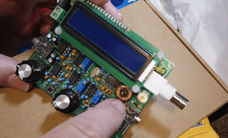
Didn’t watch the video and won’t based on comments. But that radio in the picture is a QRP labs CW transceiver and they are incredible. If you want to see how documentation of a project is done very, very well you should check it out. There are super detailed instructions for building the kit then amazing documentation about the design rationale, diagnostics and anything else an ignorant RF experimenter like me could want or need. Also the instructions on winding tortoise and transformers are too-notch. Big ups!!
Torroids. Double autocorrect fail.
The one thing to know about Toroid power transformers: don’t accidentally short them with mounting hardware. E.g. if you attach with a through bolt to a metal chassis, make sure no metal part touches the top of the bolt, otherwise a huge current will flow.
Phew! I did some fast reading of the plethora of views on this subject. It reminded me of my time as a radio & TV apprentice / serviceman and when I used to buy an Australian publication called Radio Television & Hobbies…and where each month there was a column written by one individual called “Lets buy an argument” . And it was a good read, because like the discussion here around Toroids , lots of people had different thoughts and perspectives when discussing “trick” stuff. And as we all can see, the science is indeed tricky. But look…just being able to read the comments makes you think about the “science” of toroids and transformers more that you normally would. And that’s a good thing.,