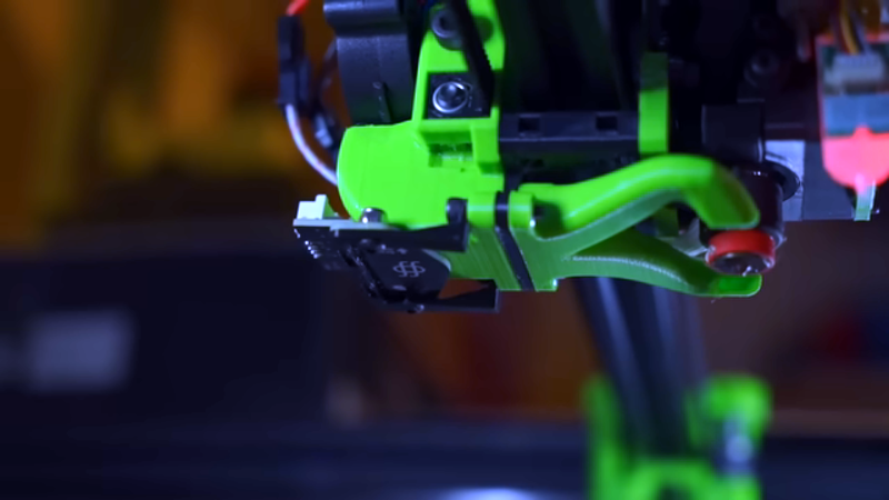
The bane of 3D printing is what people commonly call bed leveling. The name is a bit of a misnomer since you aren’t actually getting the bed level but making the bed and the print head parallel. Many modern printers probe the bed at different points using their own nozzle, a contact probe, or a non-contact probe and develop a model of where the bed is at various points. It then moves the head up and down to maintain a constant distance between the head and the bed, so you don’t have to fix any irregularities. [YGK3D] shows off the Beacon surface scanner, which is technically a non-contact probe, to do this, but it is very different from the normal inductive or capacitive probes, as you can see in the video below. Unfortunately, we didn’t get to see it print because [YGK3D] mounted it too low to get the nozzle down on the bed. However, it did scan the bed, and you can learn a lot about how the device works in the video. If you want to see one actually printing, watch the second, very purple video from [Dre Duvenage].
Generally, the issues with probes are making them repeatable, able to sense the bed, and the speed of probing all the points on the bed. If your bed is relatively flat, you might get away with probing only 3 points so you can understand how the bed is tilted. That won’t help you if your bed has bumps and valleys or even just twists in it. So most people will probe a grid of points.
Like a pixel is to a photograph, more points mean better accuracy. But it also means a lot more time since, traditionally, the printer has to move to each point and then push the sensor down toward the bed. Finding the measurement is most often a two-step process. You move fast to save time, find the bottom, back up a bit, and then find it again slowly to get better accuracy. This is necessary because the sensors don’t tell you how far away the bed is. They tell you you are near the bed or far away. So you have to move from far away to near and then stop.
The Beacon tells you how far the bed is with a claimed resolution of 0.5 microns and can sample at 1 kHz. That means you just stick the probe at some point near the bed and move over the entire bed at up to 500 mm/s, recording the distances you measure along the way. This means you can scan the bed much faster and model thousands of points.
The Beacon uses eddy currents in the bed, so the bed does need to be conductive. The company that makes them recommends bare steel with glue or a PEI coating. The plate has to be at least 400 microns thick and they warn that if you use a steel plate with a laminate, it won’t be able to sense deformations in the laminate itself, only the underlying metal. The probe is lightweight — under 4 grams — and operates up in ambient temperatures up to 110C.
If your bed attaches with magnets, you might wonder if it will affect the sensor. The answer is maybe. The company mentions that large fixed magnets can affect measurement. You can define an exclusion zone in the software, assuming that the magnets don’t eat up too much of the bed. However, the company also notes that the rubber sheet magnets typically found on print beds are actually many tiny magnets and won’t bother the sensor. You also need to mount it away from metal on your print head. The final requirement is to use Klipper since it will support the large number of points created by the sensor.
We used to resist not manually leveling the bed because it wears the printer’s Z axis, but we’ve given up and embraced it. We’ve seen another similar sensor, but it doesn’t scan — it measures in real-time.


Even with all the fancy probes now, it is still best to have the bed mostly trammed and just use the probe for warping compensation or if your bed isn’t flat. The probes are great but having the printer set up well mechanically in the first place is better than relying solely on software compensation.
Sure, and how do you verify that your tramming is good? You need to measure it, and a bed probe can do that easily. Nothing forces you to use handtools for the job, or that the bed probe info must *only* be used for software compensation.
This, I leveled my bed just by using the Bltouch and watching the 3d bed image, the bltouch now is only for the bed warp that is pretty bad and impossible to fix mechanicaly.
Voron Tap
I don’t see the point. Is the manufacturer suggesting that if you had more points on your bed surface plot, you would get more reliable layer 1 adhesion? Do they demonstrate this in any way? If your bed is such a crappy surface, it needs this kind of high-resolution scan, doesn’t that just mean that the bottom of your parts is going to have similar faults? And if so, wouldn’t repairing, resurfacing, or replacing your bed be a better solution? Are we going to see an atomic force sensor next, to get down into the nanometers?
Indeed. What is one meant to *do* with this information?
Few funny things,
1. The firmware just can’t handle these many points in the correction mesh, so all the high resolution is just noise.
2. The nozzle and sensor are independent, so if you change the nozzle you have to manually set the z height.
Klipper handles the number of points easily, as stated clearly in the article and the video. And the nozzle offset is just like any machine tool with a changable head, you need to calibrate each ahead of time. Nothing special about this particular tool.
Not everyone is still running Marlin 1 on an Arduino.
I’m still running Marlin 1 on an Arduino.
But upgrading to a 32-bit board AND Klipper are both in my long term plans….
Lots of people are already there though.
I don’t know. Might just be over-optimizing. Might not. If it’s getting all those points faster then a regular low-res scan using the normal methods I’d still call that a bonus.
Or.. maybe one night working on a project you want to get done you will warp your bed in a head crash and this will allow you to finish up even though the corner drug store that is the only business open this time of night doesn’t carry heated beds. I mean.. the corner drug store really? Maybe in 1985 you can just walk in any time and ask the friendly cashier to go grab you a new print bed from the back shelves but here in good o’l 1955 you are going to have to wait for the slow ship from China! Or at best, if you are lucky enough to have one nearby you will have to wait for regular hours when the local MicroCenter opens. You should be thankful for that hi-res bed scanning future boy!
So… basically the same as a pinda probe, but with analog output, and much harder to mount? Doesn’t seem like much of an advantage.
I did sone analysis of it myself as I was interested in how it could work. I think they’re using a High-Resolution, High-Speed Inductance-to-Digital Converter wired to a Atmel ATSAMD21.
double coil (on a 4 layer board) -> converter -> Arm (on a 2 layer board)
They went to a lot of trouble to black out some of the IC names in the pictures but in others they forgot. The converter is fairly specialised but also easy to find, but I didn’t want to mention it to avoid chinease clones.
The general idea is that it’s a lot quicker to setup and measure than a physical probe that has to go up down, up down, and doesn’t need to retract the probe when it’s finished like a bltouch.
The increased resolution is more of a bi-product with the speed being the more important thing.
The reason for doing it is usually the initial layer, too close and it smooshes into the base and sticks too much, too far away and the layer can lift at the corners or just come loose altogether.
After that initial layer it matters a lot less.
I’ve got a cast iron surface plate at my hackspace that I need to figure out how flat it is and I’m thinking I might be able to use this method to do the same thing.
$80.00 bucks? No way!
Oh what a time we live in! I remember when it was easy to spend more than that when building a RepRap just on the bearings!
Something was mentioned earlier about Z axis wear. I have a 450x450x600mm printer with a rather beefy, 2 motor Z axis. The bed has warped so I’ve been considering auto leveling but for tall prints, the Z mechanics are going to be very busy with possible premature wear. One solution to this might be to gradually reduce the auto leveling so that after x number of layers, auto leveling ceases. So I’m wondering, do any of the current slicers or auto levelers support this … maybe mods or plugins?
Pretty sure the bed mesh is only used on the first couple of layers with Klipper and after that it flattens out, you’ll have to check the docs. This is something that’s done in the printer so no, the slicers don’t need to support or even know about it.
That is correct. Layer height of the first few layers is mangled to bring it back to flat.
I suppose if you are really concerned you could use a raft and throw away the imperfections.
In Marlin UBL you can specify at what layer to stop correcting. From the docs:
G29 [F<Linear>]
Fade height. (UBL only! For others use M420 Z)
Fade the amount of Mesh Based Compensation over a specified height. At the specified height, no correction is applied and natural printer kinematics take over. If no number is specified for the command, 10mm is assumed to be reasonable.
One thing my son mentioned the other day to me is that, in theory, if you had a fixed bed mesh you could feed it to the slicer who could then generate specific G-code. You could also postprocess your G-code. So even if your firmware doesn’t do it, it could be done but I’ve never actually seen it done that way. Of course, there are downsides to that if you want to save and reuse your gcode, but if you are like me and discard all the gcode after printing it would be perfectly fine to do it that way.
Interestingly, if the vendor would make a post processor like that, it wouldn’t have to depend on clipper. You could have huge meshes processed on the PC. You’d only need to measure the bed, save it on the PC, and then filter the Gcode before you send it over….
I know that RepRap Firmware has the option to do this. You can even set how many layers it takes to smooth out the compensation.
Thanks! That’s what I was hoping to hear.
Got a rat myself and his bed mesh looks just like mine, ive talked to several machinists and they wont touch it. Was actually told to “lay it on s concrete floor and rub it around a bit” to level it out.
Ill let this simmer a bit but always looking to upgrade the RAT500 so will be getting one for certain.
“lay it on s concrete floor and rub it around a bit” Interesting concept.
My bed is warped up in the center by 0.007in (.18mm). I discovered this by attaching a dial indicator to the head since I didn’t have a probe. I have yet to try this, but instead of concrete, I plan to use a granite surface plate (very accurate surface) covered with various grades of sandpaper sheets, and just lap it down. Has anyone tried this? But I wonder if honing or lapping it while cold will remain flat when heated to 100C? My bed came as a 450 x 450 x 1/4in (6.35mm) thick aluminum plate but after some inquiries, I found it should have been a cast 1/2in (12.7mm) plate.
I’m an aerospace machinist and would never suggest using a concrete floor as a leveling bed. Granite surface plate with sandpaper with a little water underneath to suction the paper to the plate would work. On large plates like 450mm technique will be key though, too much pressure on one point will introduce its own out of flatness.
Absolutely, and Im not even a machinist but I was like… excuse me? I know Im in “the south” but I expected more from someone in that biz. XD my bed is the 500mm RatRig and Id rather not fucc up a bed thats more expensive than a whole damn ender machine. The wetsanding maybe but id need a huge sheet.
I still prefer to use the nozzle drectly as sensor, just like the new MK4 does. Seems to make the most sense that you can just swap bed surfaces, and nozzles, without having to go and recalibrate the correct Z offsets every time. Sure, you can save a minute of bed probing by scanning everything super fast, but then you spend 2 minutes figuring out the correct offset values for the confiiguration you’re running. Maybe this makes more sense if you only print small stuff that does not take any printtime? But if you print large models, even the “slow probing” time is like what 1% of the total print time? There are better ways to increase your printer output, like increasing nozzle flow rate to actually get more plastic melted and extruded…
That’s assuming the nozzle is clean on every start of a print. With remote start I’m not sure I’d trust that. Everything has its benefits and cons. My nozzle is rarely clean if I do multiple remote prints and even when most debris is soft as the nozzle heats up it still introduces error in the system. Non contact sensing avoids that issue. But you’re right it also has benefits. But the con is not just the speed which you rightly point out is not a significant chunk of print time anyway.
Can this be used to scan it as its running? Could be useful for spaghetti detection if so, then it would actually be useful.
That would be tricky, since it is offset from the nozzle, and it requires moving the whole printhead down to where the plunger contacts something. It would require a bit of logic to avoid hitting part of the print with the nozzle.
In fact, now that I think about it, this is a problem anyway: the plunger has to extend down to a point lower than the nozzle in order to be displaced by the bed as the printhead is lowered, without causing the nozzle to hit the bed. So the plunger has to be lower than the nozzle. So what happens when you’re printing, and the printhead is moved to a position that causes the detector plunger to coincide with the print? I don’t see how this isn’t a constant problem.
Hello Wes! Looks like you’re the guy I’ve been looking for if you don’t mind a few questions?
Never thought of using water to hold down the sand paper, if it doesn’t soak through, because I’m thinking of using graphite, carbon paper, or maybe layout blue from time to time on the surface I’m lapping to check my progress. Any thoughts on what I might use that wouldn’t clog up the sand paper? And speaking of that, what grits would you start and end with … paper or cloth? I bought a can of repositionable spray adhesive used on stencils but not sure if it might interact in someway with the granite plate. And lastly, if you’re still with me, there’s a heating element on one side of the 1/4″ plate that I heat to 100C when printing ABS. I’ve read somewhere that if you machine, or maybe sand, the original surface of an aluminum plate, it’s physical characteristics can be altered. So what’s you’re thoughts on whether it will stay flat after sanding and heating?