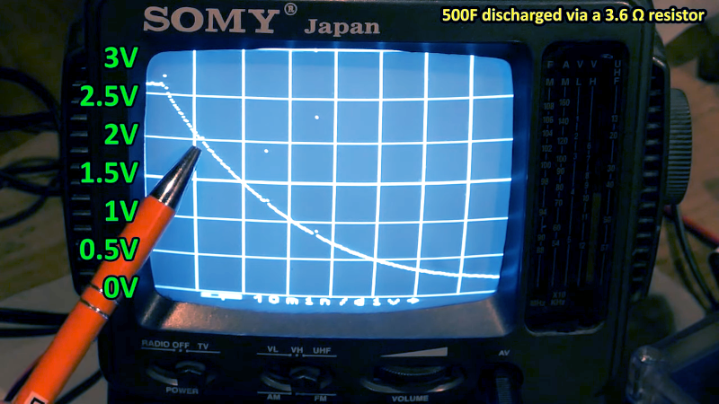
We’ve always been a little sad that supercapacitors aren’t marked with a big red S on a yellow background. Nevertheless, [DiodeGoneWild] picked up some large-value supercapacitors and used his interesting homemade oscilloscope to examine how they worked. You can watch what he is up to in his workshop in the video below.
Supercapacitors use special techniques to achieve very high capacitance values. For example, the first unit in the video is a 500 F capacitor. That’s not a typo — not microfarads or even millifarads — a full 500 Farads. With reasonable resistance, it can take a long time to charge 500F, so it is easier to see the behavior, especially with the homemade scope, which probably won’t pick up very fast signals.
For example, A 350 mA charging current takes about an hour to bring the capacitor up to 2.6 V, just under its maximum rating of 2.7 V. Supercapacitors usually have low voltage tolerance. Their high capacity makes them ideal for low-current backup applications where you might not want a rechargeable battery because of weight, heat, or problems with long-term capacity loss.
The real star of the video, though, is the cast of homemade test equipment, including the oscilloscope, a power supply, and a battery analyzer. To be fair, he also has some store-bought test gear, too, and the results seem to match well.
Supercapacitors are one of those things that you don’t need until you do. If you haven’t had a chance to play with them, check out the video or at least watch it to enjoy the homebrew gear. We usually look to [Andreas Spiess] for ESP32 advice, but he knows about supercaps, too. If you really like making as much as you can, you can make your own supercapacitors.


Thanks for post :-)
As a practical personal example of just how good these are I’ve been using 6 off BCAP3000E Maxwell super-capacitors (Yes 3000 Farads each) in series equals 500 Farads, since 2016 ie for 8 years or to start a 2.2L 4 cylinder 1997 Apollo and another 6 in a 2.4L 4 cylinder 1997 Mitsubishi Van just fine, negligible degradation :-)
The only two issues are:-
1. Charge retention over more than about a week to 10 days if not driven. So I use a small solar panel & regulator to keep them topped up to a total of around 14.7v (could be a bit higher) – which is close enough to the alternator charge voltage, so when the engine starts there isnt much alternator power to recharge the capacitors ie avoiding incoming charge surge etc
2. Dont leave the lights on when engine not running (only 15mins :/ ) and dont have the radio on for more than a couple of hours or so on high volume, otherwise not enough to start engine. Though both being manuals easy to start on an incline. Did get caught a couple of times so ideally adding a low voltage warning of impending loss of power would be useful Eg a low power cpu that calculates time remaining – couple of leds to warn eg red/green blinkers (for such as two attempted engine starts) given measured rate of current consumption for accessories ie the lights or radio/phone charger etc Since its force of habit haven’t put a processor in though its on a growing list – priority highly variable !
Looks like development of combining super caps with batteries is accelerating, couple articles on phys.org re micro fabrication at semiconductor level promising…
Why the CPU? These are capacitors, so just put a voltmeter and mark the voltage corresponding with the energy needed for one or two remaining engine starts. The movement of the instrument indicates current draw and shows spikes which go unnoticed otherwise, and which may be a sign for upcoming failures, if they suddenly start to appear. No additional hard- or software needed.
Hmm, thanks for question Matthias “Why the CPU?”
Primarily prediction value eg my point “Eg a low power cpu that calculates time remaining ”
To clarify detail:-
a. For precision in assessing time remaining ostensibly to asymptotically arrive at best assessment without guessing, ie potentially getting caught with insufficient power, there’s more utility value in measuring energy delivered over a suitable period of time than just voltage ie Integration…
b. Just using one dimension such as voltage doesn’t get around it rising once the load is removed or otherwise perhaps being erratic from noise, ie At the least capacitor Equivalent Series Resistance (ESR) is one aspect as well as leads too – though to a lesser degree
c. Temperature swings whether from engine bay or cap self heating (ESR) is another, also winter to summer extremes etc
d. Logging the cap efficiency and degradation value over time
e. By selecting a suitable CPU and only 6 voltages to measure for 6 caps in series then you can report looming out of charge potential on worst cap – then have option to swap out a much lower capacity cap that might discharge so much its voltage reverses – potential for catastrophic failure.
f. Also re e. These days can report that via wifi or ble to a smart phone etc
g. Option for tutelage, as in education in a group project illustrating how to go from concept to outcome and in the dynamic of a group training in sharing efforts etc
Few others of course, over to you :-)
Cheers
Ok:
a. on a capacitor the voltage tells you everything about the contained energy: E=1/2 C*V^2
b. if you see the voltage rising on removing the load, then you have either drained the capacitors below the minimum charge for a start attempt within a very short notice, or the ESR prevents any starting attempt anyways. The moving coil meter will tell you immediately by its motion and warn you about excessive electromagnetic noise and/or lack of shielding and avoiding electromagnetic interferences
c. the way the meter moves will give you a good feeling for the quirks and needs of your capacitors in boundary conditions and during normal operation
d. on a test bench you can use a monitoring system for gaining data points to present in the documentatin, yes. During daily use watching the movement of the meters will give you a good or even better feeling for what is going on.
e. moving coil voltmeters may replace the balancing resistors and give an excellent comparison of the capacitors state at a glance during normal operation. The CPU will have to employ a galvanic separation for each cap to measure, need operating power and on top the balancing resistors.
f. ok, do it this way for a short lived one-off, and keep in mind you either bin the whole project as soon as you need a next generation smart phone, or replace the smarts by a real measurement device
g. as I said somewhere else on this site not too long ago, use microcontrollers to figure out the best way to do it in real life, but keep in mind that the development is not complete as long as you need a microcontroller to do basic things as monitoring a voltage
That’s the spirit! 🙂👏 Not sure if he’s a licensed amateur (doesn’t matter), but that dude represents true ham spirit! That’s how amateur radio used to be, I think:
Up to date operator, but also still using DIY equipment, keeping a general fascination for electronics, technology, physics etc (not just radio).
Also thumbs up for giving that little CRT monitor a new purpose. Despite being old, they can still be a useful part of your shack/electronic lab.
Super capacitors are quite nice for some applications.
Though, the “Their high capacity makes them ideal for low-current backup applications” isn’t always correct.
There is generally two groups of super capacitors.
Those that are designed for energy storage. These usually wins on cost/farad or farad/volume, but often have “high” ESR.
And those that are designed for peak power. These don’t have particularly good cost/farad nor farad/volume but have very low ESR in comparison.
My guess is that this is likely just a difference in metal film thickness. The metal film doesn’t contribute to capacity, but does contribute to current handling. A thicker metal film takes up more space and also costs more in itself.
I remember the term “goldcap” from 10 years ago or so. It was used quite often.
Never heard of “super caps”, until recently, though.
Anyway, self-discharge might be a problem.
An CR2032 button cell can last for 30 years for battery-backed RAM.
Super NES and Gameboy cartridges etc.
A super capacitor surely has a higher self-discharge.
The high capacity types may do nicely as a battery substitute for electric wielding, I suppose. :)
Super capacitors have been used for both SRAM backup and RTC applications since back in the 90’s. However for applications where one often relies on mains power, the capacitor is more there for short term backup, usually though only for a few minutes to a couple of hours.
In regards to self discharge, this is usually only a couple of µA per farad at worst. So typically going to last a few hours per volt dropped. But the device getting powered is the main limit to runtime, since its current consumption typically dwarfs the self leakage.
However, a lot of applications don’t use super capacitors as the primary energy source. But rather as a short term backup, often to ride through shorter power outages. So self discharge is almost irrelevant. Other than the passive power consumption to keep the caps topped up. But as stated, that is a couple of µA per farad, so not a much power to speak of, even in a large capacitor bank.
A fair few datasheets for super caps don’t even specify leakage, since that is how irrelevant it is.
“Goldcap” is however Panasonic’s brand name for some of their super capacitors.
But “super capacitors” is technically a casual way of saying “double layer electrolytic capacitor”, but that is a mouth full, so “super cap” it is. People are simply lazy.
Thank you very much for your explanation! I really appreciate it! 😃👍
““Goldcap” is however Panasonic’s brand name for some of their super capacitors.”
Ah, I see. So it’s like with Q-tip (cotton swap), Tempo (paper tissue), Plexiglas (acrylic glass), Aspirin (acetylsalicylic acid)..
I just wonder why I haven’t heard the term “super cap” back then. Were the Goldcaps so very popular ?
Wow, Somy oscilloscopes are the best!
That oscillascope is giving me Max Headroom vibes.
I know, right?! 😃
What’s great about those simple scopes: They can measure over a long time.
While a normal oscilloscope is meant to help with real-time stuff, these homebrew scopes can technically measure for days, weeks.
They’re like modern day alternatives to mechanical oscillosgraphs.
That reminds me of one of my favorite tinkering book from ~90, btw. It described how to use a DOS PC w/ gameport (analogue) as a long term scope. It could draw a chart, an oscillogram on screen, and save it as picture to file.
Back then, this was fascinating, because you could graphically see how, say, a temperature sensor picked up the change in temperature.
A light sensor, say an LDR or photodiode, could also be attached. Or a microphone, to analyze how traffic noise changed over the day. The possibilities were huge. Measurement of a capacitor was possible, too, of course.
Hm. I’m not sure if that’s relatable to modern hackers, still. Back then, it was simply fascinating to build something yourself from spare parts. While others already had invented something similar, it was still a fascinating experience.
The mid-90s and before were a time in which you could still impress others with your homebrews. You could even sell little gadgets (say, radio modems for RTTY/SSTV/PR or composite frame grabbers or relays boards for PC) and kits all by yourself in your shop in your village or ask a tiny, local TV/radio store to sell it for you.
You could even make your own original packaging using cardboard or sell the kit in a plastic bag with a photocopied 2-page “manual” you wrote yourself on a typewriter.
Nowadays, I think, we have much more capable technology, which is both good and bad.
The good thing is that we can realize about any project we want to, the bad thing is that we can’t build the main parts with out bare hands anymore, that we can’t use substitute parts.
If a specialized chip we need is nolonger for sale, we’re screwed.
Let’s think of the Raspberry Pi shortage, for example. Projects that boot directly via SD can’t be run on other SBCs.
Discreet parts like LM386, NE555 or the early processors were different. A Z80, M86000 or 80286 was produced by numerous manufacturers, partly via licensing agreements. Same goes for the CGA/Hercules graphics chip, the 6845.. Or MCUs of the 8051 series.
That’s one of the reasons, why, say, the Arduino IDE with its libraries was so refreshing when it was new, it a bit of provided hardware-abstraction. Projects could be adapted for different boards. Similar to the homecomputer days when programs were largely written in Basic, with a bit of peek/poke here and there.
Okay, enough for now. I just tried to explain why using DIY tools was so fascinating at the time.