In the days of CRT displays, the precise synchronization between source and display meant that the time between a video line appearing at the input and the dot writing it to the screen was constant, and very small. Today’s display technologies deliver unimaginable resolutions compared to the TV your family had in the 1970s, but they do so at the expense of all their signal processing imposing a much longer delay before a frame is displayed. This can become an issue for gamers, but also with normal viewing, because in some circumstances the delay can be long enough for it to be audible in a disconnect between film and soundtrack. It’s something [Mike Kibbel] has addressed with his video input delay meter, and it makes for a very interesting project.
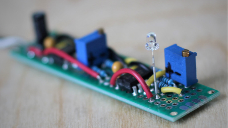
At its heart is an FPGA, and in the video below the break he goes into great detail about its programming. It both generates a DVI output to drive the monitor and performs the measurement. The analog to digital converter side of the circuit is interesting, he has a photodiode and an op-amp driving a comparator to form a simple 1-bit converter. He takes us through the design process in detail, with such useful little gems as the small amount of hysteresis applied to the comparator.
There are probably many ways this project could have been implemented, but this one is both technically elegant and extremely well documented. Definitely worth a look!


We have a couple of cool designs, where do we submit them?
Instructions are at the linked “OP AMP CHALLENGE” banner at the bottom of the article.
this delay stuff makes me sad. sometimes there’s something to get angry about, like a poor implementation decision. but underlying it all, it seems like a hard trade-off. asynchrony is so obviously useful and inevitable in so many ways…but man! we used to be able to tell a priori the exact interval between a specific instruction and a specific display result. i don’t want to go back — i never want to buy another crt for as long as i live — but i often miss what was lost
One thing I miss is being able to have the same TV program on in different rooms when working in different areas. Now, each TV has its own delay and the overlapping sounds makes the house a big echo machine
This! It’s useful enough with radio, but with video it was great. Especially since you didn’t need to crank the volume to overpower all the other sources of noise if they were watching the same thing. It was also nice when phones were the same way. The only delay you’d notice is if someone was far away from you.
To the question that nobody asked: why a comparator when this circuit could be done with dual op-amps just as easily? Answer: op-amps make poor comparators. They may latch up when driven from rail-to-rail and take extra time to recover from saturation.
Indeed, this is why I used a comparator for the second stage. I now realize I didn’t mention that detail in the video or write-up. Good catch! Another important detail is the usage of an op-amp with CMOS inputs in the first stage. The MCP 6291 I chose only has a +/- 1.0pA input bias current. The photodiode produces a very small current (tens of nA), so it’s crucial to keep that current flowing through the i->v resistor and not into the op-amp!
That little detail has bitten me many times. “Why does my sample and hold circuit not hold!?”
Also, a little detail: often the + input has lower bias current than the – input. I forgot why.
Indeed, this is the reason I used a comparator in the second stage. I now realize that I didn’t mention this detail in the video or write-up. Good catch! Another important detail is that the op-amp in the first stage has CMOS inputs with a tiny +/-1 pA input bias current. The photodiode only produces a small current (on the order of tens of nA), so it’s crucial to make sure the current goes through the i->v resistor and not into the op-amp input!
I love the 1-bit dac! The first time I encountered 1-bit converters, it was in the datasheet for an old TI part that I got about 30 of from a Goldmine-Elec unsorted surplus box about 10 years ago. The code was something like TMS3477, a recorder/playback chip which had some kind of speech synthesis if I recall correctly
Nice! I love it. As it would happen I built a similar circuit to enable me to measure the duration of a really beefy electric spark where I didn’t want even a magnetic coupling to my scope for fear of transients (discharging a 240uF capacitor charged to 3kV) but an optical detector with tunable threshold and hysteresis fit the bill (and could be knocked together from parts on hand). Sometimes nothing beats those basic building block chips like op amps and comparators :-)