It’s rare in 2023 for an instrument to be entirely analog, instead it’s more normal for a front-end to feed the analog-to-digital converter (ADC) in a microcontroller. Typically the front-end will do the job of transforming whatever the output range of the sensor is, and present it to the microcontroller in whatever range it accepts. [David] had exactly this problem with a pH sensor, and rather than buy an expensive module to do the job he designed his own.
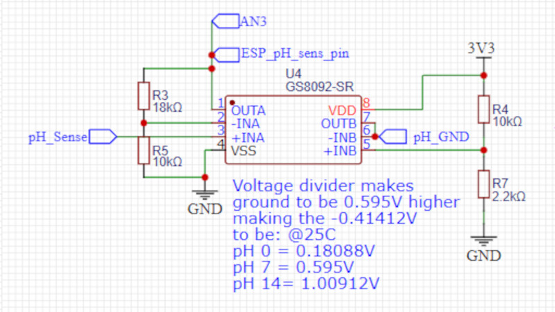
The sensor in question produces a relatively tiny voltage of -0.414 to +0.414 volts, and requires a very high input impedance. A FET input op-amp is selected, with the ground of the sensor shifted upwards into the positive range by a voltage divider. This then feeds a second op-amp that amplifies the resulting DC voltage for the microcontroller input.
This circuit is an especially simple op-amp application, and is a typical one for a sensor interface where a DC voltage needs to be brought into range of a microcontroller. If you’re not used to op-amp circuits then take a look, this type of analogue circuit is not difficult and might just save your butt some time.
Want to know more about simple op-amp circuits? Have we got the video for you!


I have a book from school with all the standard OP applications.
PID, P, I, D and all kinds of amplifiers e.g.
That is nothing to enter a contest with.
BUT if someone draws an operational amplifier as a square with pin numbers, maybe there should be a special category in the context: “My first OP-Amp!”
The symbol is for the IC from the parts library, not for the circuit component. Do you want to go around drawing your own custom symbols, or do you just want the job done?
> Do you want to go around drawing your own custom symbols
Exactly, yes. If you know how to do it it’s a job that will take 10-15 minutes tops. If you don’t know how to do it, you should learn because you will need to do it anyway for any serious work. The time investment in making a readable schematic will easily pay for itself when it avoids confusion and mistakes later on. Having a nice symbol will also allow you to straighten out the wiring around it.
If you’re going to publish your design, it’s also a courtesy to your readers. If there’s 1000 viewers spending 15 seconds each trying to decipher the mess, you will have wasted 4 hours of time.
Also, some people will simply give up, and not even study the design when it looks like this, so you’re missing out on potentially useful feedback.
My definition of serious work is not faffing about the aesthetics. If you’re paid a dollar a minute and more – or not paid because you’re doing a proof of concept in your spare time as is the case – I wouldn’t bother.
You can ask, would you pay someone else $10-15 to draw you a pretty symbol that gets used exactly once?
Also, the deadline is yesterday.
Besides, as someone else pointed out, the symbol layout in this case matches the physical part, so when you’re designing the circuit you can already start to see the upcoming physical layout in the schematic stage, which saves you time later in routing it.
What’s this blasphemy of drawing a dual opamp as a rectangle symbol?
+1 and as long as we are piling on, despite the manufacturer (Gainsil?) labeling pins INA and INB in the dual part package, INA is usually the label for an Instrumentation Amplifier!
So, how does that pH electrode feel about having its ‘ground’ elevated by 0.595 volts above the power supply ground? I hope there isn’t a current path from power supply ground to the liquid being measured.
I particularly like the accuracy they have achieved with resistors. Very impressive.
And the use of a symbol matching the physical device gets extra points.
Sorry to be cynical, but this shouldn’t be on Hackaday.
This circuit is just for some amplification and adding bias, the calibration is done in software as it says on the project page. After all, you can’t control the input offset of the individual op-amps either so it’s pointless to specify 0.1% resistors etc.
The general rule for analog design is that you phone it in as badly as you can get away with to save on parts cost, then calibrate or trim to get it lined up. That’s a tradeoff that depends on which is cheaper: components or the calibration process. Here the emphasis is on low parts cost.
The reason it should be on Hackaday is because it illustrates simple low-cost design in a space where things often get overly convoluted and difficult, and the questions related to getting things down that way. You can do things elegantly, accurately, well, or you can just get the job done to satisfaction – and that’s literally what a hack is.
This is literally a TI app note.
Unfortunately, the TI app note identifies the many sources of error when dealing with pH electrodes, including issues with PCB layout and here we don’t get that information.
No accuracy requirement or spec is shown for the project so I guess any old opamp will work, right?
it’s 59.16mV / pH step at 25degrees C for these sensors, so an input offset voltage of just +/-6mV is an error of +/-0.1pH.
Input bias current goes up, a lot, with temperature. I guess no operating temperature spec is shown for the project, so any old op amp will work. pH probes start at 300 Megaohm and go up to 1 Gigaohm or so. That’s why input offset current matters so much when measuring pH. Vsignal drop = input offset current * sensor resistance.
The circuits are extremely sensitive to current leakage, so much so that it’s not unusual to see flying through hole parts soldered in the air so as not to leak current through FR4, degrading the input signal.
If this was a pool product you’d need reinforced isolation between any high voltage power source and this sensor board.
The above is why parts like the LMP7721 exist and to a lesser extent, the MAX40110.
They say it’s a project proposal. So yes, any old op-amp would do because the specs don’t really exist as of yet. It only needs to work somewhat to showcase what can be done.
My guess is they’re throwing in a very cheap op-amp and the “secret sauce” is characterizing the output and compensating in software for temperature and all that. They don’t care about any of the design issues, they just want to make one that works and then see how it works.
Btw. this is a very good design principle against copycats – make an intentionally bad design with omissions that you can fix in software. The copycats don’t know what makes your stuff tick, so their copies of your product will end up working extremely poorly.
This is a terrible design. Clearly this guy hasn’t actually used it. Or he would have figured out that -414mV is not 0 pH in fact it would be pH ~14. From the (ideal) probe (@25C) 0mV = 7 pH, -414mV = 14 pH and +414 = 0 pH. So the voltage he states are completely wrong.
Here’s our entries for the challenge! (I don’t know where else to post them)
https://www.robots-everywhere.com/re_wiki/pub/web/Cookbook.2pin2motor.html How to use two bidirectional pins to control two motors. Also does level shifting. Uses a LM324 or similar op amp.
https://www.robots-everywhere.com/re_wiki/pub/web/Cookbook.AudioSerial.html Very simple way to control things with cheapie Android phones. This is old and made more sense when bluetooth adapters were more expensive. Uses any op amp, really.
‘Dude’ keeps arguing valid engineering points so I’ll just say ‘amateurish’ and leave it at that. Best of luck in the real world.