With the availability of precision controllable actuators, it’s easy to overlook the simple but versatile mechanisms that got us here. In the video after the break, [Teaching Tech] explores the basics of cams and how to use them in your projects.
Cams are used to convert rotation into linear motion, and are probably best known for their use in engines and locking mechanisms. [Teaching Tech] first goes over the basic design and terminology in CAD, and demonstrates it’s use with a cam follower, locking mechanism, cam plate, and a knob that snaps to predefined positions. Of course a cam shape is not limited to a single lobe, but can have multiple lobes of various heights to create different motion patterns.
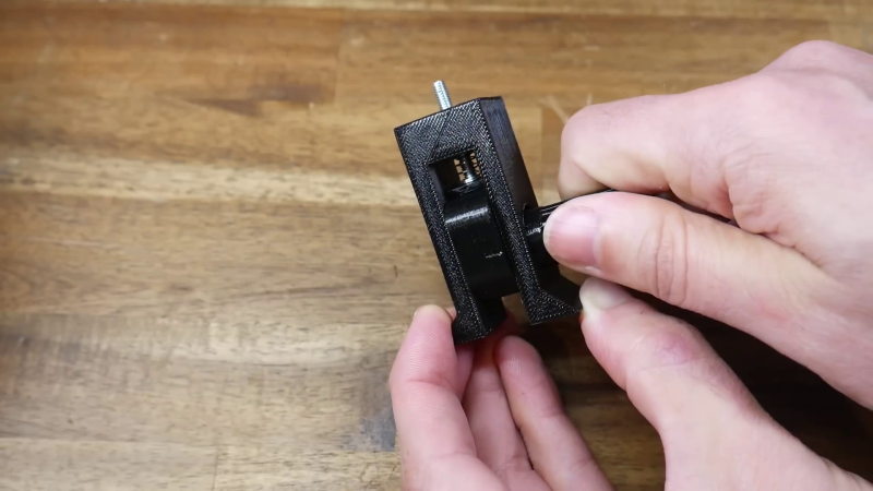
Cams are especially useful when you need to operate multiple mechanisms from a single input drive, as [Teaching Tech] demonstrates with the 3D printed automaton of a polar bear attempting to swipe a seal. We’ve also seen cams on a mechanical 7-segment display, and they were used to safely fire machine guns through aircraft propellers up to the 1950’s.
So next time you’re thinking adding another actuator to a project, take a moment to consider if a cheap and simple cam could do the job.


So it’s not the end of the cam era ?…
Here’s your coat.
I would disagree about cams being simple to design. The shape of the follower (flat, roller, arc) has quite a large affect on the relationship between angular position and lift.
The no-maths workaround that I have used for this is to use CAD to draw the follower rotating around the base circle every few degrees, then join the tangent points with a spline.
ie, draw the system with the motion inverted, with a static cam and rotating follower and join the dots.
I imagine software like Mechdesigner or Dynacam is used for CAMS.
https://psmotion.com/mechdesigner/feature/cam-design-analysis
Isn’t that just minkowski() with extra steps?
Minkowski just translates right? It doesn’t rotate the outer piece?
Plus that would just tell you where the follower would be, not where the base circle needs to be to make the follower be in a certain spot.
minkowski() can take a negative value, can’t it?
This is indeed an extremely simple introduction to cams. Cams are used in many more different configuration, and a quick search for “cam mechanism” will find many more variants.
Also note you can buy “cam rollers” as standard industrial components. They are a combination of a ball (or needle) bearing with a thicker and stronger outer race, and a bolt in he center. Quite often these cam rollers are used in a narrow slot, the slot can push the roller forward and back and you don’t need a spring for the return action.
A cycloidal gearbox is also a (quite ingenious) cam mechanism…
Analytix Cams for a surprisingly affordable (for engineering software) price.
https://saltire.com/analytix/cams.html
Reminds me some videos by Tim Hunkin :)