If you do any kind of machining, 3D printing, or PCB layout, you probably have at least considered buying a pair of calipers. Old-fashioned ones had a dial and were mechanical devices, but lately, digital ones have become quite affordable. We keep meaning to tear a set of ours apart to see what’s inside, but thanks to [learnelectronics], we don’t have to — the video below provides a fascinating look at what’s inside a cheap pair of Harbor Freight calipers.
Honestly, it doesn’t seem like it would be that hard to figure out how far down a bar you are. The trick is the caliper has to be super accurate. Oddly enough, the cheap calipers examined use capacitors as a sensing element.
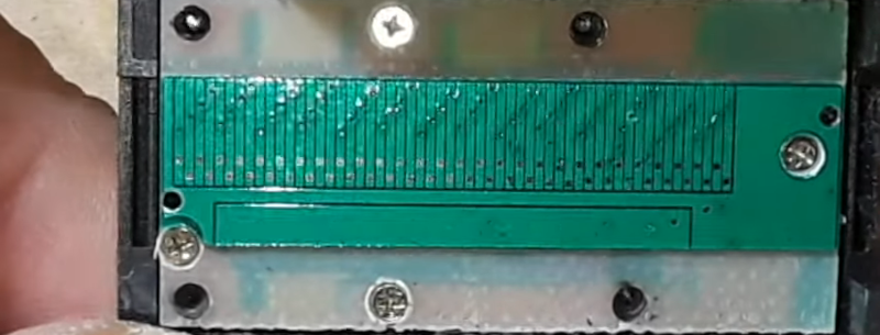
There is a long flexible PCB stuck to the sliding part with conductive pads. The display unit is also a printed circuit and manages the battery, the display, and the other half of the capacitive sensor. If you want a more detailed explanation of how the sensor actually works, check out capsense.com. If you note, the pattern on the sliding part has traces that look like a square wave, and half have a different phase than the other half. These are the sine plates and the cosine plates. A 100 kHz signal flows through the capacitor, and it is possible to read the direction of travel and the amount of travel easily.
The calipers are very accurate, but it’s possible to improve them. A more practical project is to make them communicate with the outside world.


Thanks! Now I don’t have to pull mine apart 😁
Could have googled for the picture. He didn’t explain squat.
https://www.grant-trebbin.com/2014/04/digital-calliper-teardown-and-repair.html
How it works: the thin bars in the slider send out an 8-phase AC signal that jumps capacitively to the T-shaped bars, and then back to the slider through the long strip below the thin bars.
The different spacing of the bars creates an interference pattern that either passes or cancels out the AC signals sent in, resulting in a single-phase AC signal at the output. The peak-to-peak amplitude of the signal goes from zero to maximum over a tiny movement of the slider, let’s say that is within 1 mm of movement: the sensor knows its absolute position within this one millimeter as finely as it can measure the analog signal amplitude, but it doesn’t know where along the long strip that millimeter is.
The peak-to-peak amplitude of the signal represents the sine of the interference pattern. The DC bias (middle point between pos and neg peaks) represents the cosine of the pattern – or vice versa. The CPU knows which way the slider is moved by observing which of the two is leading and which is lagging between subsequent signal cycles, and when one crosses zero it knows to increment or decrement whole millimeters relative to the last known position.
The calipers are never turned off. It’s always pinging the sensor to see that the last known position hasn’t changed. When you turn the power off, it simply shuts down the LCD – nothing else – because the actual measurement uses so little energy that it doesn’t need to.
The inaccuracies that apply to the system include:
-humidity, temperature and dirt change how the signal jumps from the slider to the slide and back, altering the signal amplitude
-mechanical play between the parts changes the distance between the slide and the slider, altering the signal amplitude
-manufacturing tolerances introduce random dimensional variations along the slide, changing the interference pattern or signal strength (e.g. thicker and thinner glue under the strip).
What? Do you know where to find the chip? What I see is a serpentine Inductor strip and inductive pickup that averages over several “lazy loops” of an Inductosyn. Drive the serpentine with a sine and calculate the phase angle of the induced signal to get a full cycle with each twist, or hundreds or thousands of divisions per loop.
This is how the position is encoded for massive telescopes and gun mounts. No bearings or other parts besides the shaft of the main machine. No optics. https://www.maccon.com/rotary-linear-encoders/magnetic-encoders/inductosyn.html
Huh. It looks like the method is not Inductosysn but something much more complicated. Developed way back in the 70’s or 80’s to get around the Inductosyn patents. Anyway, the 4 pads in the little door are ASCI outputs. You can make a DRO out of it.
Hey, one other person who knows besides me and Nils Ingvar Andermo that seems to understand that digital Vernier calipers ARE NOT CAPACITIVE SENSING. Capacitors are present, but they are emphatically not having their capacitance measured. If they were any twist, or movement of 0.000001mm would throw off it’s readings. So no, it’s not capsense. Never was. That is a 100% false statement.
Nils Andermo invented many variations according to his patents. The one that is in use that works the same in your 15 dollar amazon special as well as your Mitutoyo 200 dollar ones is a slight cheapening on what “Dude” explained. No, the older or more accurate patents are NOT found in Mitutoyo or Starrett — it’s the same method as the 15 dollar ones with slightly better power saving electronics for the “off” state.
It is a travelling “AC” signal that moves over multiple fingers but in the 1980’s making an AC signal was hard. Instead it’s a prescribed patter that “flips” the capacitive accumulator to store charge every cycle and a psuedo PWM. Then eventually a low bit count (3 – 6bit) ADC to interpolate between to give the higher precision. This means that even if there is twist, bend, vibration, it’s all read quickly in an fairly EMI and mechanical tolerance immune way.
Almost every digital measuring device, including digital micrometers, use the same method because it’s insanely cheap, accurate, and doesn’t require crazy manufacturing tolerances to make it work well. But even the link above doesn’t “understand” how it works. “Dude” does. I spent days on the patents with hopes of replicating it for a project with modern microcontrollers. Nils was/is a genius at using capacitors for coupling in a time when ADC’s, accurate timing and high powered microcontrollers were expensive. Things that made capsense hard and no advantage over Nils original work for measurement.
Agreed. Thanks for the pointer to a more explanatory article.
Where’s the fun in that?
“calipers are very accurate” – you mean “guessing stick”?
micrometers are accurate, calipers have a bit of resolution – try push a little heavier on the whole assembly.
Casual confusion of resolution, precision, and accuracy is common, and can be confusing when the context isn’t clear. Accurate is also relative: Compared to what?
Calipers CAN be fairly accurate and precise relative to machinist requirement with proper setup and care in use, certainly for initial setup &c, but generally can’t be terribly good on either, no matter what the resolution is. This is fine. You WANT higher resolution than accuracy of precision, if you can get it, as long as the resolution isn’t mistaken for the others.
Failures, especially with lower end models, are due to Abbe’s principle, uncontrolled measuring force, and improper setup (gib play, for example). Improper setup includes not zeroing for the measuring form used (inside, outside, step, depth), as, even on top quality tools, they NEVER all zero together.
(still use vernier calipers daily, as they don’t lie and have no hidden magic to fail invisibly like digital and dial)
Since when is math “hidden magic”?
Try using “hidden Markov models”.
It’s not the math that’s hidden magic, it’s the batteries and chips. I’ve got two digital callipers which have failed in some way – one just eats batteries so is a design fail for me; it’s always dead when I pick it up – and the other randomly resets.
Dial ones I’ve no experience of, but I’d guess there’s a risk of play in the cogs???
A few failure modes I have seen on dial units: tension springs fail, teeth skip in the gear rack from dust and chips, often both directions so rechecking zero doesn’t show it, pinions or gears can be bent eccentric leading to cyclivc errors, rack sections can be misaligned on longer models, leading to a step error at the transition, corrosion from coolant leading to tooth-to-tooth errors.
All with good quality units. A shop can be a rough environment.
I run a small CNC machining business making small medical device parts. I use both digital and dial calipers; the digital are nice when I want both inch and metric measurements, and the dial are more precise. With dial, you can see differences of about .0001″, and of course it’s good practice to check accuracy against gauge blocks.
Yes, I have micrometers for when tight accuracy really matters, but for larger sizes the calipers are much more convenient.
That’s a simplistic and flawed over-generalization.
I have sitting before me:
One “Chuan Brand” Chinese micrometer that I’ve owned for 35 years. It has 0.01mm marked resolution, that I can read to half of that, but no calibration certificate.
One set of genuine Mitutoyo 6″ Absolute Digimatic calipers, again with 0.01mm resolution, calibrated to +/-0.01mm accuracy across its range on outside measurements. They also read in inches, with similar specifications. I have the certificate.
One genuine Mitutoyo Absolute Dial Test Indicator, with 1um resolution, a specified accuracy of +/-0.003mm and a specified repeatability of 0.002mm. No cert.
One Brown and Sharpe BesTest Dial Test Indicator, 0.002mm resolution. No cert.
One Starrett 25-111 Dial Test Indicator, 0.001″ resolution. No cert.
Which is the most accurate?
Ignoring the fact that most of these tools have different uses, on the face of it, the calipers are the most accurate because I have a certificate proving them so.
Now, I could put the DTIs on a height stand on my surface plate and use them to make comparative measurements of a selection of Starrett Webber Croblox gage blocks at my disposal, and I’m confident that all would prove to be accurate to +/- 0.005mm or better with a similar repeatability. If I were to pay to get them calibrated to NIST standards then they would pass muster too. They are all high quality DTIs in good condition.
The micrometer has a spring-loaded ratchet to set the measuring force. The DTIs are spring-loaded to set the measuring force. They are used to measure materials where the deflection of the object being measured is negligible under that force. You can buy lower force versions for measuring softer materials.
Calipers usually have a thumb wheel to aid in setting a measuring force. Your apparent inability to use that correctly is no reflection on the accuracy of the calipers. For a start, that affects repeatability not accuracy anyway. You’re only supposed to use enough force to take the measurement without deflecting the object. For a hard strong object, such as most metal objects, you’re not likely to be able to exert enough force to detect any deflection, but a sheet of paper or cardboard is a good experimental test subject. It’s hard enough that you can get a nice firm repeatable reading, but soft enough that you can easily cause deflection if you overdo it. If you can learn that feeling then it will set you in good stead for measuring most things of interest. Just be aware that the softer the object, the less force is needed.
For giggles, I just used my calipers and micrometer on a 0.300″ Croblox gage block. The micrometer reading was 7.635mm. The calipers 7.62mm. I took the caliper readings in metric mode, and took both measurements before calculating the Imperial equivalent to ensure that I remained ‘blind’ to any personal bias. 7.62mm is 0.300″ exactly. 7.635mm is about 0.30059″. Ignoring any temperature effects (the calipers/micrometer were in a 74 degree room, the block came out of a 68 degree garage), I’d have to say that it appears that the quality calipers are indeed more accurate than the cheap micrometer.
I want a digital caliper with a display on the opposite side from where they all have it. they’re backwards for measuring diameters of work on lathes. With the jaws down and the body of the caliper towards the operator, the display is on the left side where it’s difficult or impossible to see. Dial and vernier calipers are the same way. Why has this wrong way around design persisted for so long when it should be obvious they should be the other way for use on a lathe?
Or are the lathes all backwards since the headstocks are all on the left, the workpiece is on the left, thus it’s easiest to apply the caliper to the work with your left hand, other than the readout then facing the wrong way to see it.
Several brands make left handed calipers. They are more rare and expensive, but on the plus side, the cheapest and crappiest brands don’t make them.
Alternatively, you can use a caliper with a data output. Either wired, or RF (There are some bluetooth models too). And with an external display (phone?) you put the display in a convenient location regardless of caliper orientation.
Oops, that was supposed to be a response to Timo (below).
Hmmm…time to make a cheap DRO sensor for my lathe and mill.
There exist kits to use cheap digital calipers as X and Z gauges for a central DRO for a lathe, although they usually require drilling through the (usually hardened steel) jaws for accurate and robust mounting. But as cheap as DRO’s have gotten (which are the same thing only without the jaws) it’s pretty hard to motivate a DIY effort. I got a cheap one that exceeds my needs for under $80, with a 12cm and a 65cm pair of linear encoders and a head unit with typical lathe kinda math functions.
Sorry, but i have to say i hate these digital callipers. Here at our department we have a few of these, but their batteries are always empty and then they are useless.
If somebody finaly changes the battery the next guy forgets to turn it off and tomorrow the battery is empty again.
We have one mechanical calliper and it is the only one working reliable.
Fight me! ^^
I’ve had a few of the cheap ones and they were all garbage.
Then I bought a mitutoyo and it just keeps working.
The Mitutoyo does not have a “power off” feature, and I’m glad of that. Sometimes I forget it for a day or a week, but normally I do turn it off, and I think I’ve been using it now for 4 or 5 years. There are some video’s with comparison between the real and the fake mitutoyo’s, (from clough42 to Mr AvE BumbleFuck) and one of the differences is the current consumption.
The Mitutoyo also has an “absolute” function, and this is a double plus good feature. You never have to re-zero the thing. Just turn it on and it still knows it’s position. Always. Those calipers which forget their position when they go to auto power off (after a minute or so) are really annoying.
I also have a few analog / venier calipers (also Mitutoyo), but I’m past 50 now and can’t read them anymore without reading glasses.
I got a pair of harbor freight digital calipers when HF first opened in my area in the early 1990’s, that have absolute positioning. I don’t know how they do it. All my subsequent ones reset every time I hit the power button. And that old pair have a battery life measured in years. My only frustration with it is that after 30 years of daily use, the power button has begun to fail and I can’t figure out how to take the body apart without damaging it. When the power button fails completely, I guess I’ll find out.
Even the cheap $15 calipers from Amazon remember position after auto-off. Thats because theyre never truly off. Auto-off just means turning off the display. Where are you finding digital calipers that lose their position?
That’s not necessarily an advantage for cheap calipers because that kills the battery life. The measurement circuitry typically uses much more energy than the display. I’d rather have to re-zero at every power-on, as long as the auto power-off had a reasonable timeout such as 5 minutes or more.
Mitutoyo absolute calipers work differently. They actually have an absolute induction-sensing linear scale rather than a relative one, so they do know their absolute position at any time and are immune to overspeed errors as a result. I believe that they drop their sampling rate significantly after a period with no change in position in order to conserve battery life, and there is no auto-off.
I have an old harbor freight one from 6 years ago that still has the original batteries and the spare in the case. Every other one I’ve seen does exactly what you are talking about
I have a few different HF calipers from over the years, and it seems they made changes. The oldest one (>10 years) eats batteries but has the least wobbly movement. The newest, which is remarkable for its much larger LCD, runs for a couple of years on a battery but has some play in the movement.
There seem to be a few different circuits on the various cheap calipers. Some drains the battery in no time while others lasts forever and a day on the same battery.
My experience is to look for the ones using a CR2032 lithium cell and does not have auto-on feature (i.e. as soon as you move the slider – or bump into the table – they turn on).
The ones using a 1.5V coin cell and/or has the auto-on feature, they tend to drain the battery in no time.
At least, that’s the experience with the handfull of calipers I have come across…
Or store your caliper in their convenient carrying case so it’s not turning on randomly when not in use.
Mine with auto on and off using a CR2032 battery has lasted me 1 year then 2 years on the two batteries that came with it. The first year it saw a lot of use fixing stuff on a car and it was often left in the car or my garage – so a fair amount of auto-on vampire drain. The past 1.5 years, I’m still using it as often, though mostly with electronics work, and I put it back in the case when I’m done.
I added a single SPST DIP switch to mine so I could turn it off completely when I put it back in the case. It is completely self-contained in the caliper body, no unsightly wires or hot glue anywhere:
http://www.surfacezero.com/g503/data/500/medium/Digital_calipers_added_on_off_switch.png
That’s awesome
I printed a single AAA battery holder (https://www.thingiverse.com/thing:456900) and soldered wires through a connector to the battery connection tabs on the calipers. I just hotglued and ziptied the pack to the calipers…so it looks classy af.
To be clear, I disconnect the JST style connector when it is being stored.I should have added a switch, though.
Same thing, no switch, but with a single-AA holder. Happens to be exactly the same length as the black plastic display box.
Soldered two wires for power, applied hot glue, and I haven’t had to change the battery in > 5 years so far.
I skipped the battery holder and just soldered the battery. It lasts a really long time with a rocker switch.
What internally did you modify or do?
Turning them off doesn’t do much. I once measured their current draw and it was something like 12uA when on and 10uA when off.
Despite looking identical there are dozen of variations of the typical cheap Chinese caliper, including one magical version that does match Mitutoyo in having very low current draw and batteries that last for years. Must be what @AnotherMaker has.
The 3v lithium cell versions apparently last longer. Oddly a pair I bought to test out only show 0.1mm, not the usual 0.01mm.
That’s because you are using the wrong battery. You need the SR44, the cheap LR44 lasts a fraction of the time.
You’re right on with that but trying to find a decent battery of any type is a challenge IMO. Most leak internally long before they should expire. The tell-tale is a bulge on the positive side; if it doesn’t sit totally flat and rocks even the slightest, it’s done.
Aside from buying way overpriced retail packages, it’s a real challenge to find non-counterfeit name brand batteries online.
Maybe they need those radioactive diamond batteries?
my cheap ones do this so I leave the battery out when not in use.
I have a Mitutoyo where the battery seems to last forever, but the same is also true for my Micrometer.
I bought digital calipers 3 years ago that use a coin cell battery with auto off (and no backloghting). Came with two. The first I replaced about a year after buying it. I’m now at the point where I need to replace the second. If your batteries are dying in days, weeks, or months, there’s something wrong. Just replace the whole thing – I only paid about $25 on Amazon. Your employer has probably wasted much more than that in employee time dealing with replacing batteries if your description is accurate even after accounting for hyperbole.
Assuming everyone carries their smartphone at work, you don’t even need to worry about having flashlights available if for some reason, you’re using these in a dimly lit environment.
Forgive me pointing it out, but… no love for the BigClive video from some years back on this very selfsame subject?
<3
https://yewtu.be/watch?v=fKSSY1gzCEs
Also BigClive video is better. I had one that ended up in the trash.
“… you probably have at least considered buying a pair of calipers”
Why do I need 2?
I have a Starrett digital that i bought 27 years ago, and it still works fine. It was around $399.00 back then. It is not built like this one in the video.
Hello. is there any way that you could make the caliper longer, say 500 or 600 mm, it would be easy enough with a piece of 16 x 3mm flat bar , I just need it to read over a much longer distance.
I was thinking of adapting one to be used as a measure on my table saw sled, replace the actual vernier part with some aluminum plate, bolt on a piece of aluminium so it looks like a L letter and then you can use that to push the wood against as a stop on a table saw sled. If you could do it table saw sled measuring life would be easier !
“Of course there’s always gonna be one”, while stripping a screw. Then: “Alright, bigger bit, no problem”.
First: those are of course famous last words. :D
Second: why not start with the right fit of bit to start with, and not strip that screw in the first place?
You all know the truth in my words. ;)