The best part of I2C is that it is a bus that is available just about anywhere, covering a vast ecosystem of devices that offer it as a hardware-defined interface, while being uncomplicated enough that it can also be implemented purely in software on plain GPIO pins. Despite this popularity, I2C is one of those famous informal standards that feature a couple of popular implementations, while leaving many of the details such as exact timing, bus capacitance and other tedious details to the poor sod doing the product development. Thus it is that we end up with articles such as a recent one on the tongue-twisting [pair of pared pears] blog, covering issues found while implementing an I2C slave.
As with any shared bus, whether multi-master or not, figuring out when the bus is clear is a fun topic, yet one which can cause endless headaches. One issue here comes from a feature that the SMBus version of I2C calls quick read/write. This allows for the rapid transfer of some data. Still, depending on the data returned by the slave, it may appear to the master that nothing is happening yet, since SDA is being held low by the slave until the stop condition, essentially locking the bus.
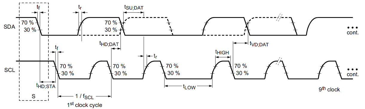
Where things get even more exciting comes generally in the form of what logic analyzers love to traumatically call a ‘spurious start/stop condition’. This refers to the behavior of SDA and SCL, with SDA going low before SCL indicating an error. This can occur due to a hold time that’s too low, causing other devices on the bus to miss the transition. Here SMBus defines a transition time of 300 ns, while I2C calls for 0 seconds, but it’s now suggested to delay calling a start/stop condition until a delay of 300 ns has passed. Essentially, it would seem that implementing a hold time is the way forward until evidence to the contrary appears.
The third pitfall pertains to the higher-speed modes of I2C, including Fast-Mode (FM) and Fast-Mode Plus (FM+). Backward compatibility with these higher speed versions is absent to spotty. Although FM+ (introduced by NXP in 2007) is supposed to be backward compatible with slower speeds, effectively the timing requirement differences between the FM+ and FM standards are too large to compensate for. At least in the current versions of the standards, but one of the joys of I2C is that there’s always another new set of revisions to look forward to.


Even ignoring these pitfalls, I avoid I2C as much as possible…
Me too. Devices holding SDA low because they think they’re in the middle of read access are incredibly annoying. Peripheral drivers in MCUs are always different, and often overly complicated (while still not providing a solution for first problem). High impedance nature of the bus makes it overly sensitive to crosstalk.
I’d like to take a moment to apologize to the world for leaving it littered with prototype laboratory instruments that implement an I2C connection over micro-USB cables.
I was young(-er), stupid(-er), and needed locally sourceable cables that could deliver 2A and provide two lines for data. I at least had the good sense to only do it with 5V boards and had +5V and GND on the standard pin mapping so nothing shorted.
I promise I’ve changed focus from designing cursed hardware to writing cursed software.
It could be worse. My lab instrument company implemented RS-232 over USB A/B cables for its $250k tools for the better part of a decade. Not USB-to-serial, just using the USB pins for serial with no labels or warnings. “But the feedthrough for USB was easier to get!”
There are also machines that use RJ45 for their own proprietary protocols. Shit like this causes so much headaches in the field, especially when machines are delivered with unique cables that look just like standard cables.
I’ve done something similar, but with D-sub connectors for GPIO. They are just so useful. They only plug in one way and have locking screws. Lots of independent conductors inside good shielding. In my defence, the GPIO port that uses a DE-9 also has a big label on it that says “NOT RSS232.”
American companies designed RS232 which is fast and robust. European companies designed I2C and CAN both of which are PITA to deal with and more often than not cripple any embedded system they are used with.
Comparing apples and oranges. Or at least apples with massively more complex and capable apples, half a century later. Stop with the stupid patriotism.
+1
It seems patriotism works better than union of mutually hostile states, each wanting only to screw others and milk as much “development funds” as possible. Name at least one EU-based company that produces metrology equipment, be it calipers, micrometers or oscilloscopes.
Rohde & Schwarz.
Your view of the EU is completely warped from reality, but that’s not surprising. You want one? Vogel, Germany. Nearfield Instruments (NL). GOM (Zeiss) Switzerland (Not EU, but in the single market). Measurements International (Czech), Airyx (Germany), Laytec (Germany), Bowers Metrology (UK – I choose to ignore Brexit!)
++1
Things like metric thread are even older yet they are still used to build epic projects like ISS. Just because technology is old dosn’t mean it’s obsolete.
FYI Metric threads are all in nice round TPI (thread’s per inch).
Just because most of the world forgets a measuring system, doesn’t mean they aren’t still using it. Tooling costs rule all. 2nd e.g. Railroads and carts have very similar wheel track.
“FYI Metric threads are all in nice round TPI (thread’s per inch).”
Really?
THREAD SIZE THREAD PITCH (MM)
M1.6 0.35
M1.8 0.35
M2 0.40
M2.2 0.45
M2.5 0.45
M3 0.50
M3.5 0.60
M4 0.70
M4.5 0.75
M5 0.80
M6 1.00
M7 1.00
M8 1.25
M10 1.50
M12 1.75
M14 2.00
M16 2.00
M18 2.50
M20 2.50
M22 2.50
M24 3.00
M27 3.00
M30 3.50
M33 3.50
M36 4.00
M39 4.00
M42 4.50
M45 4.50
M48 5.00
M52 5.00
M56 5.50
M60 5.50
M64 6.00
M68 6.00
So, 6mm being a nice rounded TPI, it should be read as 6/25.4 – ie: 60.5/256 (we still not there yet).
+1
RS232 is a point to point communication standard while I2C is a buss that can have a master and multiple slaves. But I’ve implemented RS232 over 3000 feet of wire. It was slow, you could watch the characters march across the screen, but it worked.
Try that – I2C…
RS-485 enters the room… ;)
@Gamma Raymond said: “RS-485 enters the room… ;)”
Using RS-485 (actually TIA-485 today) only gets you half way there via the physical layer. You still need some sort of protocol to run on that physical layer; that might be called the link layer and it would probably accomodate some sort of media access control (MAC) addressing.
RS-485 does not define a communication protocol; it’s merely an electrical interface specification. Although many applications use RS-485 signal levels, the speed, format, and protocol of the data transmission are not specified by RS-485. Interoperability of even similar devices from different manufacturers is not assured by compliance with the signal levels alone.[1]
The EIA once labeled all its standards with the prefix “RS” (Recommended Standard), but the EIA-TIA officially replaced “RS” with “EIA/TIA” to help identify the origin of its standards. The EIA has officially disbanded and the standard is now maintained by the TIA as TIA-485, but engineers and applications guides continue to use the RS-485 designation. The initial edition of EIA RS-485 was dated April 1983.[1]
1. RS-485
https://en.wikipedia.org/wiki/RS-485
Yep, ran I2C round a military camp as a remote display bus system, back in the ’80’s. Quite a lot more than 3000′ of wire in the system.
It worked fine, you just have to know what you are doing, and you have to understand the possible fault conditions, and design to clear them.
Sadly quite a few semiconductor makers couldn’t make a working I2C peripheral to save themselves (looking at you atmel). Bit bashed interfaces are often more reliable, and sometimes take less code, by the time they work reliably in difficult systems.
I, on the other hand, try to use it as much as possible.
I always try to use MCU’s that are as simple/cheap as possible, mostly resulting in a (to) low pincount.
with I2C it’s very easy to add a small display and use I/O expanders.
don’t know of another solution. (SPI is more complicated, with a bunch of devices on a bus)
You should look up LIN bus. Its 1 wire + GND for power and data. Its basically a mini CAN bus, with error correction and all (missing bus arbitration).
I2C is good for communicating with a lot of devices slowly. SPI is good for communicating with few devices quickly. I2C tops out at 3.6 MHz I believe, SPI I have seen up to 80 MHz but can probably go much faster. Also SPI has other modes like dual, quad and octo SPI that increase throughout further, making it much more suited than I2C for high throughput applications like flash or RAM chips hence most microcontrollers that use external flash use some for of SPI for it including ESP32, STM32 and rp2040.
To reduce the number of pins needed for chip select when using SPI, you could use a decoder or mux/demux chip, that would let you select a single slave at a time. 4 microcontroller GPIO pins could get you 16 select pins with a cheap, commonly available mux/demux chip. You could also use shift registers.
I’ve seen some analog divecies spec their adc’s at 250Mhz Spi and even in some fpga’s. With quad spi & dual data rate (ddr), it can do 1Gbps
I2C also allows the slaves to totally power down all clocks, even while the bus is active. MCU clock only needs to run during code execution, not while every other device on the bus is talking.
This is great in low noise and low power systems.
Not a word on I3C ?
inter inter integrated circuit?
Improved Inter Integrated Circuit. Also, 3 is one more than 2.
I’ll see you, add raise you 4,
Idiodically Incremented Incoherent Inefficient Incognito Inter Intergrated Circuit
I7C
Isn’t the buss on SD cards a version of I2C – with 4 data wires? Wouldn’t that be I4C?
Will have to look that up now. Pretty sure I saw it in a Hackaday post, some time back.
@Alan
I would guess SD cards use some fancy SPI variant with multiple data wires, but i think the specs for this are not public (stupid!). SD cards also support “simple” SPI mode, but with less speed and it’s not that easy stuff to implement/debug.
I always though SD cards used a variation on SPI. You can use them with basic SPI but there are other versions of SPI with more data lines. You can get dual, quad and octo SPI with the corresponding number of lines although it then isn’t really a serial interface. You will commonly find them used with flash or RAM chips.
The full spec is paywalled tanks to MIPI.
well, the first pitfall of this article is the use of the terms “Master” and “Slave”…
:D
“Producer” and “Consumer”.
^^ Too “Disney”.
I thought it was “controller” and “peripheral”, so ambiguity right from the start…
Controller and Target. Every protocol got their own replacement terms.
Unfortunately, this change has made me screw up several designs – “what is MOSI now???” I can’t believe how much time I spend trying to make sure it’s right.
Agreed. A peripheral can be a master, a slave or both. And a slave can be some type of controller (PID controller).
I thought it was now “Main” and “Secondary” so you can keep M & S markings.
I think that’s what SPI uses. I2C went with Controller and Target.
There are a wide variety of terms now, and they are industry and company dependent. I’ve seen producer/consumer, initiator/responder, manager/subordinate (nice parallel there), host/device (borrowed from USB), and controller/peripheral.
That’s incorrect. An I2C slave can be a sensor, an actuator or memory. You can argue a sensor is a producer since it produces a value, but also a consumer since it consumers a measurement. Same with an actuator. Memory is neither producer or consumer, but an intermediate storage for produced things to be consumed later. A master controls a slave as it generates the clock signal and sends commands (read or write). The roles are clear.
Master and Servant
B^)
Or how about employer and easily-interchangeable-meat-bot?
Least it’s not Master and Commander.
This is probably the best alternative.
Never saw the problem with Master and Slave in this context. Still use the terms as needed….
That’s the whitest thing I’ve ever heard
That’s the most racist comment I’ve seen on HaD.
You do realise that more people than just people from Africa experienced slavery? Slavery has existed pretty much from the point when humans existed. Yes they were the most recent but they were far from the only ones. Pretty much every race has been enslaved at some point.
There is no problem, they are just words. Every race has been enslaved at one point or the other and you can probably still find slaves in some places in the world. People need to stop being so sensitive, none of the people complaining were ever slaves.
Nothing wrong with those terms, afterall how would you like to have orders shouted to you at 400KHz and only one wire on which to reply, and only then when the master permits it. And if you are late to reply the whole thing freezes up and you get the blame.
Also, for those who do obsess against the conventional terms, could you atleast pick replacements which start with the same letters. “Manager and Servant”, “Main and Secondary”, “Monarch and Serf”? The very worst is those who tried to get the master and slave references out of SPI, and did it in much a way as to mess around not only the lettering but even the orderof the MOSI and MISO acronyms to become PICO and POCI, not even leaving the order of master and slave in place and so making documentation an absolute ngihtmare to follow.
One should’ve never coined “master & slave” for this usage.
=
“It” should have been called one of the alternative sets of terms from the start…
:-)
And Volta should have called the negative terminal positive. But that’s all hindsight. Once something is established it cannot be undone.
Bruh.
I don’t think this is about gender, more about history and stuff.
However i still use “master” and “slave” and i don’t see any problem with that. We are talking about *electronics*, not about *people*…
We’re talking about criticism from the same people that believe a brown paper bag and waking up to go to work everyday is somehow racist.
Or branches in a repository. Somehow people chose to feel offended about that too (yes feeling offended is often a choice). I’ve had repositories break because of this political correctness.
“Overseer” and “Indenturee”. “Whipper” and “Whipped”. Compounding this is the “Male” and “Female” pin connectors.
“Overseer” and “Indenturee”. Oh please no! How would we ever pronounce the pin names for SPI (OOII, OIIO)?
EIEIO!
B^)
Male & Female is a bit crap as well. Plug & Socket (or Jack) works better.
HA. I was thinking the same thing.
PS: I think the whole slave/master debate and lots of current politically correct thing stupid :)
This is where LIN and CAN shine. CAN bus especially when it comes to bus arbitration.
Isn’t CAN a bit heavy for inter-chip comms on the same system?
Definitely and a good part of the CAN goal is to cyclically transmit process data, which simply isn’t part of I2C/SPI, it’s definitely a different kind of bus… there’s obviously some overlap but the use cases are definitely different…
The people that suffer using I2C and SPI are the ones that try to do software without owning a scope.
It’s why I finally bought me one ;-)
I have a scope, but for I2C monitoring, I use a Logic Analyzer :-)
That’s fine until you encounter the problem I had recently. The transfer really messed up. Frequently the slave didn’t even recognise its address, and when it did SDA would sometimes do funny things near the end of a byte. Turned out it was seeing clock pulses where there were none because the rise times were too long, and it would often acknowledge a later byte before it had all been transferred. The scope showed a lot that the logic analyser didn’t.
At the end of the day every digital signal is just an analogue signal, the difference is how it is interpreted. So when sending a digital signal you still need to consider the wire or transmission line as an analogue system.
In that vein, the Saleae Logic is worth its (light) weight in gold. The protocol analyzer in their software works very well, especially if your I2C bus is heavily traveled, such as with a graphical display. It’s the smallest test instrument I own, and possibly the most useful.
Indeed, I have the same one :-)
34 channels, 500 Mhz …
Easy solution to I2C’s “issues” – use SPI whenever possible. A good SPI/I2C bus MUX rarely locks up.
Then you enjoy SPI’s many different issues.
However, there is lot to be said for using bus switches in I2C, when they are not strictly needed.
Just because you can multidrop a whole system on one bus pair, doesn’t mean that you should do it. Especially when you have segments that are slower, longer, go to noise or EMP pickup points (front panels and displays), have mcu based slaves that can crash or lockup , etc, etc.
Clock stretching is another major pitfall. A lot of devices depend on it, but many microcontrollers don’t support it.
Salvador Dali was a pioneer of that concept!
I appreciate this pun. :)
Except that clock stretching slows down the bus. Dali was more about melting clocks, which seems closer to overclocking… :)
Einstein wrote several excellent papers on it.
Doesn’t RPI not support clock stretching?
Microchip has had many, many MCUs with I2C hardware (MSSP) issues.
You’re better off using a software implementation of it whenever possible.
Most MCUs won’t support SMB extensions, but will do I2C.
SPI can be better, however you have to watch out for all of the different slave devices that may require different SPI settings. More annoyingly, the display controller IC’s that allegedly support SPI but then don’t work if any other peripheral is also on that SPI bus.
MSSP works fine as long as you blindly follow the appnote and its state machine. Try to be clever and write your own driver from the register spec alone and you’re gonna end up punting an ICD puck three across the room.
Affirmative!
The only pitfall I had with I2C was with target ICs with limited address setting capability and wanting to use more than the number of allowed addresses. You either end up with bus expanders or using more cpu ports for enable or extra I2C ports.
I have to admit i once ran I2C across an entire room to connect a lot of sensors (spoiler: don’t do this or at least use twisted and/or shielded cable!) and i ran into this address problem. My solution was a small µC for each node that translated between the “big” bus and the local sensor. I managed to just squeeze a software I2C implementation (master+slave) into the iirc 1k of Flash. Worked fine (almost, as i said above).
That is a very common and annoying problem. It is especially annoying when using devices that don’t let you change the address at all.
One device like that I have come across are common magnetic absolute encoders, the AS5600. Yes they have an analogue output and pwm output but you also can read the output and angle through I2C. If you want to use multiple then you are limited to using the analogue or PWM output and relying on your microcontrollers ADC or pulse timing capabilities rather than just reading the values through the ADC in the encoder which is already there and 12 bit. A microcontroller usually has limited ADC and timer channels but you can connect a lot of devices to the same I2C bus, this is even worse when using an SBC which doesn’t have an ADC and even more limited timer channels, being able to read all the encoders through I2C would be much easier but every device has the same address.
I can understand not having many addresses for uncommon sensors where a system is only likely to use one, but for something like encoders where a robot is likely to use many of them it doesn’t make much sense to have a single, unchangeable address.
Struggling at the moment to bitbash I2C Slave for an Attiny10 as part of my job. Keep running around in circles and achieving nothing. Glad to know it’s not just me that its giving grief.
If anyone’s got any suggestions or starting points they’d be greatly appreciated.
Here is my code for the i2c slave. It is in C++ for the Parallax propeller MCU.
It uses clock stretching. You should be able to port it.
It is used succesfuly with an esp32 master.
https://parallel.bas.bg/~yavor/i2c_slave.cpp
Make certain there aren’t any spurious signals occurring on either of the I2C lines, and that the signals are arriving as intended at the slave. Once you’re sure of those, you can rest assured that the problem is (extremely likely) in the software.
Most I2C implementations (both hardware and software) are very unreliable.
A single pulse or short on the bus can lock the bus due to an unhandled arbitration error.
And a reset of the master mid transaction can cause the slave to hold the bus.
And I’m not even talking about improper pull-up values, lack of filtering/shielding, improper termination and long buses (sometimes off the board).
Sometimes rubbing your finger on the I2C lines is enough to crash an application…
I’ve written wrappers for several I2C drivers to address those issues. One solution is trying to send a “stop without a start”, if that fails try again after sending clock pulses until it works. It can take 9 clock pulses worst case (unless I’m off by one). If that fails try re-initializing the peripheral and resetting all slaves, and if that fails reset the MCU.
Sometimes arbitration lost or infinite clock stretching isn’t properly detected so it’s always advised to add a timeout.
Proper I2C implementations wait for all slaves to be booted up after power on in software and preferably have a reset line on the slaves so a master reset always completely resets the slaves (and you can try resetting a slave if it’s not responding).
Since I2C devices often don’t have error detection I always try sanity checks on values I get back. I verify writes by doing a read. I2C is slow anyway.
I prefer SPI over I2C since that is deterministic. If I can afford the extra pins.
One real head-scratcher I’ve had with I2C was ultimately caused by using unshielded SDA & SCL lines in an environment that was electrically noisy…but only sometimes.